MARPOL ANNEX VI CHAPTER 1-3: “AIR POLLUTION AND GHG EMISSIONS FROM INTERNATIONAL SHIPPING
Leave a reply
Source: Saskatchewan Environmental Society
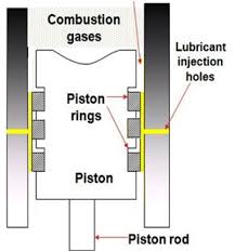
Cylinder lubrication For marine diesel engines operating on residual fuels containing sulphur, cylinder lubrication must generally serve the following purposes:
■ Create and maintain an oil film to prevent metal to metal contact between the cylinder liner and piston rings.
■ Neutralise sulphuric acid in order to control corrosion.
■ Clean the cylinder liner, and particularly the piston ring pack, to prevent malfunction and damage caused by combustion and neutralisation residues.
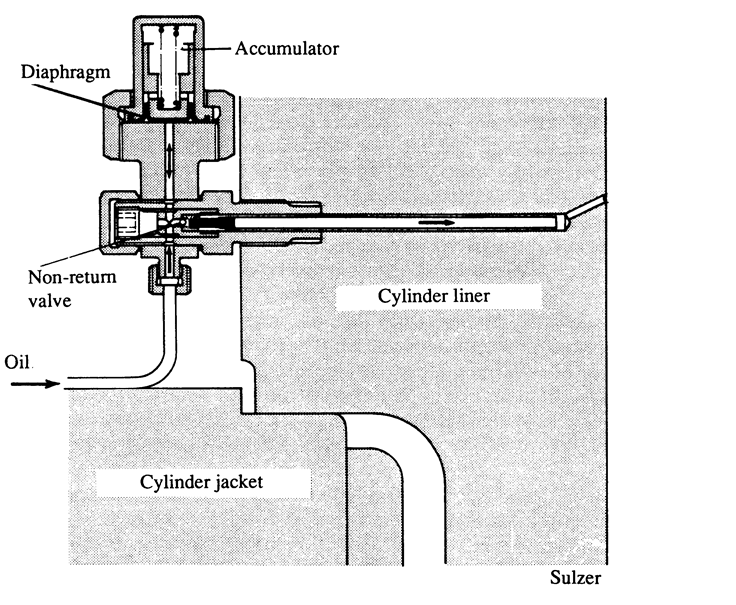
Cylinder lubricating oil for a low-speed main propulsion diesel engine is admitted to each cylinder during the compression stroke. Cylinder lubricating oil, for lubricating the piston rings and the liner, has to be admitted when the piston, piston rings and the liner are in cool condition and the piston is moving upward so that oil can be retained on the piston rings and sprayed by the piston rings on the liner walls. This is only possible during the compression stroke. Otherwise, the piston is hot and if the lubricating oil is sprayed on it, it will evaporate very fast and will not carry out any work of lubrication. At the same time, if lubricating oil is injected during the expansion stroke, i.e. when the piston is moving downwards, it will have a scrapping effect rather than lubrication.
In four-stroke trunk piston engines, there are a number of different methods for lubricating the cylinder liners and piston rings, depending on engine size and make:
■ Splash from the revolving crankshaft
■ “Inner lubrication”, where the oil is supplied from the piston side
■ “Outer lubrication”, where the oil is supplied by an external, separate cylinder lubricating device from the cylinder liner side.
In a four-stroke trunk piston engine, the cylinder lubricating oil is identical to the engine system oil used for bearing lubrication and cooling purposes.
A small amount of the cylinder lubricating oil by-passes the piston rings and ends up in the combustion space,
where it is “consumed”. However, the piston in a four-stroke trunk piston engine has an oil scraper ring that scrapes most of the oil supplied to the cylinder liner back to the engine’s oil pan, from where it is drained, cleaned and recycled.
Normally, a large, modern, well maintained four-stroke trunk piston diesel
engine will consume some 0.3 to 0.5 g/kWh of lubricating oil.
Once the correct lubricating oil is chosen the correct feed rate must be established in accordance with the engine builder’s recommendations.

The cylinder oil consumption burette is a useful means of checking the oil consumption of individual lubricator boxes to help ensure that the oil is distributed across the boxes as intended.
The volume between the two internal discs is 1/2 litres. Given the temperature density characteristics of the oil, the actual mass of the oil during
its use in engine calibration can be calculated from the oil temperature. Calibration time lies typically between 3 10 minutes depending on the oil consumption rates and the speed/power of the engine, (if the oil feed drive is speed/power dependent).
In slow speed operation, the use of heavy fuel oil with high sulphur content makes the job of the cylinder lubricant very difficult. Even high alkalinity oils cannot hope to neutralise all the sulphuric acids which are produced during combustion.
A correct viscosity is important in order to ensure the spreadability of the cylinder oil, and the applied feed rate and injected amount of oil per stroke are key factors in the delicate balance between under- lubrication and over- lubrication:
■ Under-lubrication
If too little cylinder oil is supplied, starvation will occur which might result in corrosion, accumulated contamination from unburned fuel and combustion residues, and in the worst case, metal to metal contact, known as “scuffing”.
■ Over-lubrication
If too much cylinder oil is supplied, the loss of fresh, unused oil in the scavenge ports
will be high, and the piston rings might be prevented from moving (rotating) in their grooves by the so called
“hydraulic lock”. Furthermore, the cylinder liner running surface structure might over time become closed and smooth like a mirror, and will no longer be able to retain the lubricating oil. This is sometimes called “chemical bore polish”, and when alkaline deposit build-up on the piston top land from excessive cylinder oil is in contact with the cylinder liner running surface, it can cause what is sometimes called “mechanical bore polish”. All of these phenomena might eventually result in scuffing.
The cooling system must be operated so that the piston and cylinder liner temperature is not dropped below the temperature at which the Sulphuric acid may condense on the cylinder liner.
Acid condensation depends on:
• the engine combustion pressure
• the liner temperature
• the concentration of the sulphur oxides
• the humidity of the intake air.
So, to help the lubricant in neutralising the acid, the engineer must ensure that the temperature of the scavenge air should be maintained in accordance with the manufacturers’ recommendation. Too low a scavenge air temperature will result in condensation with the risk of moisture entering the cylinders; too high a scavenge air temperature will adversely affect the combustion characteristics of the engine.
Critical to this lubrication area is the way the engine has been run in at commissioning. A good run in procedure will create a good wear in of the cylinder liner and piston ring. A good gas seal is obtained between them whereby a thin oil film provides reliable and effective lubrication.
The period and method of running in should be decided upon in accordance with the engine manufacturer’s recommendation. Even if only new rings have been fitted the running in procedures should be as near as possible to that recommended for new engines.
The running in recommendation may specify the use of a particular type of lubricant and the feed rate should be high. After running in, the normal cylinder oil will be used and the feed rate gradually adjusted until the recommended feed rate is reached.
So, the cylinder lubricating oil must create a lubricating film between the piston ring and the liner, and must maintain effective lubrication. It must also combat corrosive wear. The use of the correct lubricant and the correct feed rate for the engine load will help to achieve the best result from the lubricant.
Lubrication Of Medium Speed Trunk Piston Engine

In medium speed diesel the cylinder is open to the crank case. This means that contamination of the crank case oil by combustion products requires the oil to be different in character to that which may be used in a slow speed engine. Generally, the lubricant must:
* create and maintain effective lubrication between moving components under high mechanical and thermal loads;
* transport solid contaminants from the cylinder to the cleaning devices, such as filters and centrifuges;
* withstand heat; fight contamination, corrosion and wear; resist oxidation and thermal breakdown; keep the engine clean.
References:
1. www.marinediesels.info
2. The Running and Maintenance of Marine Machinery – Cowley
3. Reeds Marine Engineering Series, Vol. 12 – Motor Engineering Knowledge for Marine Engineers
4. Lamb’s Question and Answers on Marine Diesel Engines – S. Christensen
5. Principles and Practice of Marine Diesel Engines – Sanyal
6. www.wartsila.com

Image Credit: www.maersk.com
The Triple E Ships can be more energy efficient and more environment friendly. Triple-E (EEE) stands for Energy efficient, Economy of scale and Environmentally improved vessel:
Energy Efficiency:
Triple-E ships are designed and optimised for lower speeds. The unique hull design, energy-efficient engine and system that uses exhaust gas to produce extra energy to help propel the ship, make the Triple-E unmatched in energy efficiency.
Economy of Scale:
The Triple-E ships break the world record in container ship capacity without requiring more engine power. This design takes economy of scale to a new level.
Environmentally Improved:
The Triple- E ships, with their unique design features for slower speeds and maximum efficiency, emit 50% less CO2 per container moved. (as claimed by Mearsk Line Triple-E project).
Grams of emitted CO2 transporting 1 ton of cargo 1 km:
Triple-E Container Ship: 3g
Conventional railway: 18g
Truck or Lorry on road: 47g
Aeroplane or by air: 560g

Source: www.maersk.com
The vessels will be the most energy efficient. They will have the lowest carbon dioxide (CO2) footprint by emitting 50% less CO2 per container moved when compared to the most efficient container vessel available currently. Optimised design will allow the vessel to cruise with the maximum possible load at speeds prevailing in the industry.
The waste heat recovery system will capture the exhaust gas from the engine and use it to run the turbine to produce mechanical energy, which in turn, will be used to run a generator. It will trim down fuel consumption and CO2 emission by about 9%.

Source: www.maersk.com
The Triple-E class vessel will have a twin skeg propulsion system, with two slow running ultra-long stroke engines. Each engine will drive a separate propeller. Each engine will produce 43,000hp and weigh 910t with a specific fuel oil consumption (SFOC) will 168g/kWh. Each of the two propellers will be of 9.8m diameter and have four blades. The smaller the number of blades, the less the resistance will be, while the larger diameter propellers will produce more pushing power. The two engines and two propellers combination will generate further savings of 4% energy when compared to a combination of one engine and one propeller.
Moreover, the triple-E ship’s will be fitted with two Shaft Generator Motors with a rated capacity of 3MW each. The motors will act as variable power generation units which will save more energy.
References:
1. www.maersk.com
2. www.ship-technology.com

Image Credit: www.protec.co.uk
Novec 1230, C6F12O, (3M Novec 1230) fluid is a low global warming potential Halon replacement for use as a gaseous fire suppression agent. Novec 1230 is manufactured by 3M. This Fire Protection Fluid is an advanced, “next-generation” halon and CO2 replacement, offering a number of important advantages over other clean agents and CO2 in marine applications. With zero ozone depletion potential, short atmospheric lifetime and a global warming potential of 1, Novec 1230 fluid has proven to be the first chemical halon replacement to offer a viable, long-term, sustainable solution for marine fire protection.
The product is based on a proprietary chemistry from 3M. Its low acute toxicity, combined with high extinguishing efficiency, gives Novec 1230 fluid the widest margin of safety among all other chemical clean agents and CO2 – even at relatively high extinguishing concentrations. This makes Novec 1230 fluid ideal for occupied spaces,
including engine and pump rooms, paint lockers and communication and control centers where personnel may be exposed to the agent upon system discharge. Novec 1230 fluid vaporizes rapidly during discharge, and it is non-corrosive and non-conductive, so it will not harm delicate electronics, radar, navigation and other equipment. And, unlike foams and powders, it leaves no residue to clean up, which means that operations can continue without interruption.

Image Credit: safety1021.rssing.com
Fig: Novec 1230 total flooding system in engine room.
Novec 1230 fluid is a high molecular weight material, compared with the first generation halocarbon clean agents. The product has a heat of vaporization of 88.1 kJ/kg and low vapor pressure. Although it is a liquid at room temperature it gasifies immediately after being discharged in a total flooding system.
The product is ideal for use in total flooding applications, localized flooding systems, directional spray type applications and may be used in portable extinguishers for specialized applications. But in addition to the conventional methods of super-pressurization using nitrogen, Novec 1230 fluid also lends itself for use in pump applications because it is a liquid.
It has been used as a full-immersion fluid in a proof of concept data center cooling system by Intel and SGI[2]
Chemically, it is a fluorinated ketone with the systematic name 1,1,1,2,2,4,5,5,5-nonafluoro-4-(trifluoromethyl)-3-pentanone and the structural formula CF3CF2C(=O)CF(CF3)2, a fully fluorinated analog of ethyl isopropyl ketone.
The detail information of 3M Novec 1230 can be found by clicking the below links:
Source: www.3m.com

Impressive news from the new Prototype CNG category late yesterday afternoon: team Microjoule-La Joliverie pulled off a 2,521km/litre equivalent first attempt (imagine driving from Rotterdam to Palermo on one litre). New category, new benchmark.
The first UrbanConcept challenge started this morning. First on track was Louis Delage School from France with their gasoline car, pulling off 476km/litre equivalent to lead their category and set a new record. French Team IUT GMP Valenciennes from France have set a record of 1,323km/l in the Prototype diesel category.
DTU Roadrunners soon rode triumphantly to the top of the UrbanConcept ethanol category with 557km/l equivalent. After fire damaged their car two days ago, and with 200 hours of combined teamwork under their belts, the result was just 42km/l short of their 2014 winning best.
In Prototype gasoline, team TED from France swept into the lead, above Remmi-Team, with 2,308km/l.
The car’s internal combustion engine uses a high-pressure injection system to deliver a fine spray of gasoline and air into the combustion chamber about 25 times per second. The size of the spray nozzles and the duration of each jet (just 7 milliseconds) are critical to the engine’s performance.
The same principle applies when using compressed natural gas, except natural gas moves much more freely than liquid gasoline. The challenge for CNG teams this year is to hit just the right balance between the size of the spray nozzles and the timing of the jets. It also means fine-tuning their electrical systems. Gas purity also has a big impact on performance.
Shell Press Release.
Please follow the link for details:
http://www.shell.com/global/environment-society/ecomarathon/events/europe/2015-highlights/innovation-is-all.html
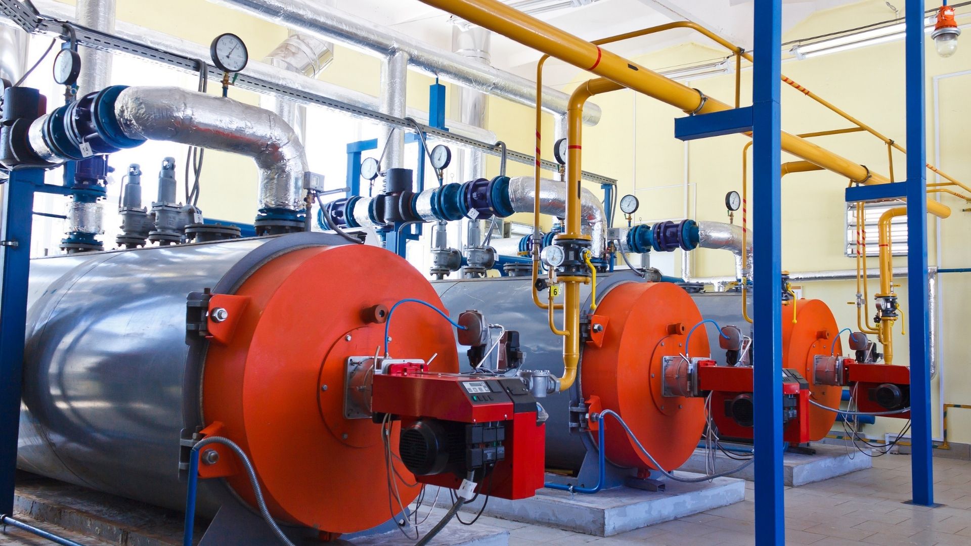

Image Credit:www.globalspec.com
Cleanliness of the heat recovery surfaces after the boiler can often be judged by observing the gas pressure differential above and below. Any significant rise in this value should be attended to. Whilst good combustion conditions will minimise the risk, deposits allowed to accumulate in this area are a fire risk and, should fire take hold undetected, it can prove impossible to control and can wreck the heat exchanger, or even the whole boiler. There is plenty of evidence of soot fires leading on to hydrogen fires.
The ignition of an accumulation of soot, rich in carbon, caused by poor combustion either in ort or when operating at low power for prolonged periods, can when supplied with the necessary oxygen be the source of a fire sufficiently intense to melt and burn steel. Air heaters, with their thin steel plates or air tubes and an abundance of oxygen, can, unless kept clean, be very susceptible to this kind of damage.
Instances have occurred in which the tubes of watertube boilers, superheaters, economisers and exhaust gas heat exchangers have, as a result of an intense fire, literally melted and run away in streams. Sometimes in the case of vertical tubes, they have melted and flowed back into their headers to solidify. According to the engineers who investigated these cases, the fires were subsequent to the overheating of tubes which were short of water or steam.
Reasons of ‘hydrogen’ fire in a watertube boiler or exhaust gas heat exchanger:
In the watertube boiler the importance of always ensuring an adequate steam circulation through superheaters has already been mentioned, and cannot be overstressed. Additionally, the firing rate, actual location of the superheater in the boiler, the inner and outer surface cleanliness and condition of the superheater tubes, and possible maladjustment of the burner equipment causing ‘flaming through’ screen tubes, can all influence the likelihood of severe overheating of these tubes.
When overheating of a superheater due to insufficient steam circulation is very severe, the tube material may ignite at about 700°C and, burning in the steam, produce free hydrogen. The iron will continue burning independently of any supply of oxygen from the air, and the hydrogen produced by the reaction will burn on coming into contact with air. This means that once such a fire has started there are likely to be two fires burning simultaneously, one, iron burning in steam and the other, hydrogen burning in air, the combined fire being self supporting and probably lasting until the supply of steam is exhausted.
The conditions necessary for the initiation of a hydrogen fire fortunately rare are generally accepted to be as follows:
1. Tube metal temperatures of over 705°C.
2. Tubes with some steam content (usually quiescent or of poor circulation).
3. The presence of a catalyst in the form of a carbon ash.
The extreme importance of adequate steam circulation was vividly demonstrated in one case where one of the two D type main boilers of a VLCC burnt out. In this incident, subsequent to a tube burst and reduction of steam pressure in one boiler, the NR stop valve shut and, before low water level shut off the fuel, a hydrogen fire started in its steam starved superheater. This white hot fire spread throughout the boiler melting and burning most of the tubes, and also initiated soot fire in the air heater. Water wall and screen tube headers were subsequently found to be blocked solid with plugs of steel which had formed when the molten boiler tubes and run back into their holes.
In the foregoing incidents with water tube boilers the source of heat responsible for the overheating has been the boiler burners. Such fires do, however, occur in finned tube exhaust gas heat exchangers and boiler economisers, where the source of heat is flue gas with a temperature much too perchance during a soot fire; the unit concerned is not being circulated, the intense heat of the soot fire, rich in carbon, may initiate a hydrogen fire and that this, as in the case of boiler superheater fires, once started, is self-supporting until al steam is exhausted.
It is important, therefore, that boiler economisers and exhaust gas heat exchangers are kept clean on the gas side to prevent soot fires, and that if defective are either bypassed on the gas side, or if not bypassed have their defective sections properly blanked off, drained and vented.
Sometimes, due to tube failure in an economiser if the individual tube cannot be isolated, or if the failures are of a multiple nature, it becomes necessary to make an emergency bypass of the economiser on the water side. Ordinarily, the gas temperature in this zone will not be sufficiently high to cause any distress to the metal parts, but there will be a fire risk due to the overheating of any deposits on the tubes. Sootblowers should therefore be operated prior to operation with the economiser bypassed, a suitable reduced firing rate should be established and the gas temperature into and out of the bypassed unit monitored, the plant being shut down at the first sign of untoward readings. Such events are also known to have occurred in diesel exhaust gas boilers and, apart from keeping them clean, a sensible precaution with this equipment is to leave the circulating pump running, after the engine is shut down, to cool down the unit and to ensure that air is not admitted until cooler conditions prevail. The only cure is prevention.
Furnace explosions or on a lesser scale ‘blow backs’ generally occur when volumes of oily vapour and air, present in a furnace in explosive proportions, are ignited, although sudden admission of air to a fuel-rich burner flame may well produce the same result. These explosions should not occur in boilers fitted with automatic sequential controls, as these, apart from controlling the fuel to air ratio also ensure adequate purging before ignition.
Even in the best designed system, however, automatic light-up failures do occur, and it is then, when going over to manual control, often in a hurry that the wrong action is sometimes taken, resulting in an explosion. Failure to obtain ignition at the first attempt must be followed by adequate purging.
Explosions in watertube boilers with their large capacity furnaces can, be a serious occurrence, often involving the loss of lives. These explosions usually occur when steaming conditions are not stabilised, as for instance during a vessel’s fitting-out period when steam is intermittently required for testing auxiliaries. At such times the operation of the boiler is sometimes a divided responsibility, and may well be under manual control without all its safety devices completely installed.
Boiler operation should always be the responsibility of one qualified engineer who full appreciates, from the furnace explosion aspect, the vital necessity of adequate pre-ignition purging, and who is aware of the possibility; especially with membrane walled boilers, of a serious furnace explosion pulling tubes out of drums and disgorging the boiler contents into the engine room.
During idle periods precautions have to be taken to protect boiler internal surfaces against corrosion. Two methods are in common use dependant on the length of lay-up.
For short periods up to say a maximum of one month, the boiler, superheater desuperheater and economiser, with all valves and cocks shut, are completely filled with hot distilled de-aerated alkaline water – daily checks subsequently being made to ensure that fullness and alkalinity are maintained.
In the second methods, used when longer lay-ups are envisaged, the boiler, superheater, desuperheater and economiser are completely dried out using heating stoves in the drums and hot air through the tubes. When dry valves and cocks are shut tight, all doors replaced (using new joints) and the boiler hermetically sealed – trays of a drying agent such as ‘silica gel’; usually being inserted before sealing up.
In the case of auxiliary boilers which operate under intermittent steaming condition corrosive conditions are likely to occur both internally and externally unless precautions are taken during their off periods.
A method frequently used, always assuming steam is available from another source is to embody simmering coils in their water drums. The use of such coils enables a slight pressure to be maintained in the off duty auxiliary boiler, thus eliminating the risk of air ingress, and the gas side is kept warm and dry.
Tube failures can occur at very inopportune moments, renewals are costly and a ship may be delayed; it is of the utmost importance, therefore, when active pitting at present, that its cause is established and obviated. In most cases, having established the cause and satisfied oneself regarding the internal condition of the tubes, it is an advantage to chemically clean the boiler so that any oxide scabs covering pits are removed, prior to re-steaming the boiler under corrected water treatment conditions.
While examining steam drums internally attention should be paid to the condition and fastenings of any fittings not removed for access purposes – internal pipes to desuperheaters, internal feed pipes, low-water pipes, low-water alarms and in particular steam driers.
The problems associated with furnace refractory materials, particularly on vertical walls, have resulted in two water-wall arrangements without exposed refractory. These are known as ‘tangent tube’ and ‘monowall’ or ‘membrane wall’.
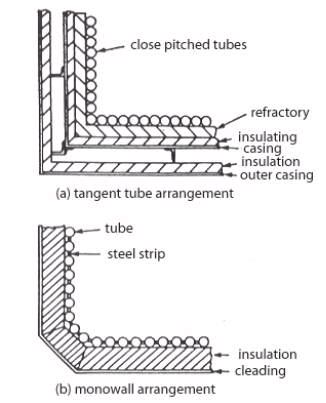
Fig 2.
Tangential and monowall arrangement
(Source: Seamanship International PC CD-ROM Engineering Knowledge)
In the tangent tube arrangement closely pitched tubes are backed by refractory, insulation and the boiler casing. In the monowall or membrane wall arrangement the tubes have a steel strip welded between them to form a completely gas-tight enclosure. Only a layer of insulation and cladding is required on the outside of this construction.
The monowall construction eliminates the problems of refractory and expanded joints. However, in the event of tube failure, a welded repair must be carried out. Alternatively the tube can be plugged at either end, but refractory materials must be placed over the failed tube to protect the insulation behind it. With tangent tube construction a failed tube can be plugged and the boiler operated normally without further attention.
Sometimes it is difficult to find the failed tube, in an exhaust gas boiler with closely fitted finned tubes for example, a method, which has found success, is ultrasonic detection.
Equipment required is a microphone pickup, connected to an oscilloscope.
• Pressurise the tube stack and headers with air.
• Enter the gas space with the microphone pick up.
• Go round the tube stack with the microphone.
• The maximum air hiss will give the maximum deflection on the oscilloscope.
• The leaking tube will be in that area.
Temporary Repairs To Membrane Or Monowalls At Sea (Ships’ Personnel)
The method of tube repair used in an emergency at sea would depend principally on whether a competent welder and machine are available. If not, the suitable plugs or expandable blind nipples for each of the failed tubes, should be available and also a supply of protective refractory to prevent subsequent burning through of the casing in way of the blanked-off tube.
(a) Welded repairs:
Welded repairs are usually of a patch nature and have the advantage that as the tube remains in use it is not necessary to protect it with refractory. A butt welded patch is preferable, but as this, and also any internally fitted patch, are liable, in the hands of an inexperienced welder, to result in weld splatter entering the tube bore, it is safer for a quick temporary repair to rely on an external fillet welded patch. For repairs of this nature the defective part of the failed tube is cut back to sound material and then a patch piece, preferably cut from a tube having bore equal to the outside diameter of the failed tube, is filet welded over the removed section of the failed tube – the overlap being kept small to prevent subsequent overheating when in service. Subject to a satisfactory hydraulic test on completion such a repair should allow the vessel to reach a port where permanent repairs can be effected (see below).

Fig 3.
Permanent welded repair
(Source: Seamanship International PC CD-ROM Engineering Knowledge)
(b) Mechanical repairs:
If a welded repair is impracticable the tube may be plugged at both ends providing the tube is subsequently protected by refractory to prevent local burning of tubes and possible the boiler casing.
Various mechanical plugging methods have been devised by the boiler designers, but lack of internal access and the high temperatures appertaining at shut down can make this an extremely unpleasant and/or lengthy operation. Two methods are described below:

Fig 4.
Permanent Mechanical repair
(Source: Seamanship International PC CD-ROM Engineering Knowledge)
Method 1. Windows are cut in the tube about 62mm from its extremities through which wires with taper plugs attached can be pulled the taper plugs having been inserted into the headers via the inspection doors. The plugs are pulled into position through pieces inserted across the windows, and are then pulled up solids by nuts.
After both ends of the tube have been plugged in this manner the whole length of the defective tube and the boiler casing behind it are shielded from the furnace heat during subsequent steaming by a thick shield of plastic refractory.
Method 2. Again windows are cut at each end of the tube through which blind nipples are inserted and subsequently expanded.
It will be appreciated that in this method boiler pressure tends to blow the plugs out whereas in Method 1 boiler pressure tightens the plugs in the hole. It is important to ensure therefore that with this method the expander rollers project down the bore of the nipple beyond the header or drum thickness so that an internal anti blow-out ‘collar’ is formed on the nipple during expanding; as a double precaution special ‘stepped’ roller can be used to form this collar.
As in Method 1, the whole length of the failed tube has subsequently to be shielded from the furnace heat.
Repairs To Membrane Or Monowalls In Port
The type of repair whether accepted as permanent or semi-permanent will depend largely on the availability of welders skilled in this type of work.
Inserting a new section
The obvious and most straightforward permanent repair consists of cutting out the defective length of tube along with part of its adjoining membranes and butt welding in a new section. This repair entails the services of skilled welders, the removal of casing and refractory in way of the repair, and accurate weld preparation.

Fig 5.
Insert repair
(Source: Seamanship International PC CD-ROM Engineering Knowledge)
It is important to note that unless welders skilled in the type of repair are available, the surveyor should insist that the welders being employed do a preliminary procedure test to his satisfaction.
Fish mouth tube replacement method

Fig 6.
Fish mount tube replacement method
(Source: Seamanship International PC CD-ROM Engineering Knowledge)
This method, when carefully executed, is also acceptable as a permanent repair and has the advantage that as all welding is done from the furnace it is not necessary to disturb the boiler casing and refractory.
The defective part of the tube along with part of its adjoining membranes are burnt out, as in the previous method. The replacement piece of tube is prepared with its top and bottom ends cut off at 45° to give access when the replacement is in position for welding, from the furnace, the rear part of the two circumferential butt welds.
When these rear parts of the circumferential welds have been satisfactory completed, wedge-shaped pieces of tube are welded into the two windows, and the circumferential butt weld then complete working from the outside. The membranes are subsequently closed by welding as in the previous method.
The configuration of the wedge pieces can be varied to suit tube diameter and access required and, if necessary, backing rings may be used.
The loose ring method

Fig 7.
Loose ring method
(Source: Seamanship International PC CD-ROM Engineering Knowledge)
In ports where it is doubtful whether the experience of the welders justifies their employment on the previous two methods of repair, it is possible by this ‘loose ring’ method, to make an acceptable repair of a semi-permanent nature using down hand welding.
In this method access has to be made all around the tube and loose rings with cupped upper surfaces are slid into position in way of the butts to be welded, so that an inexperienced welder has a better chance of making a butt cum fillet joint. In all other aspects the repair is as in the previous two cases.
In view of the extra metal thickness in way of the rings and possible build up of weld metal this repair could subsequently be the subject of overheating in service, and on that account the repair should only be regarded as semi-permanent.
On completion of any of the foregoing repairs whether temporary or permanent, the boiler should be subjected to a working pressure hydraulic test. In the case of the repairs effected in port the welds should be crack detected and, if possible, X-ray detection equipment should be used.
REFERENCE
1. Leslie Jackson & Thomas D Morton Reed’s General engineering knowledge for marine engineers (2002) Thomas Reed, pgs 89 – 136
2. Leslie Jackson & Thomas D Morton, Reed’s Motor engineering knowledge for marine engineers (2002) Thomas Reed, pgs 178 – 198
3. Seamanship International PC CD-ROM (2004) Engineering knowledge
4. www.marineengineering.co.uk
5. www.marinediesels.info