
Image Credit:www.globalspec.com
Some common boiler problems are described below:
Fires
Cleanliness of the heat recovery surfaces after the boiler can often be judged by observing the gas pressure differential above and below. Any significant rise in this value should be attended to. Whilst good combustion conditions will minimise the risk, deposits allowed to accumulate in this area are a fire risk and, should fire take hold undetected, it can prove impossible to control and can wreck the heat exchanger, or even the whole boiler. There is plenty of evidence of soot fires leading on to hydrogen fires.
Soot Fires
The ignition of an accumulation of soot, rich in carbon, caused by poor combustion either in ort or when operating at low power for prolonged periods, can when supplied with the necessary oxygen be the source of a fire sufficiently intense to melt and burn steel. Air heaters, with their thin steel plates or air tubes and an abundance of oxygen, can, unless kept clean, be very susceptible to this kind of damage.
Hydrogen Fires
Instances have occurred in which the tubes of watertube boilers, superheaters, economisers and exhaust gas heat exchangers have, as a result of an intense fire, literally melted and run away in streams. Sometimes in the case of vertical tubes, they have melted and flowed back into their headers to solidify. According to the engineers who investigated these cases, the fires were subsequent to the overheating of tubes which were short of water or steam.
Reasons of ‘hydrogen’ fire in a watertube boiler or exhaust gas heat exchanger:
In the watertube boiler the importance of always ensuring an adequate steam circulation through superheaters has already been mentioned, and cannot be overstressed. Additionally, the firing rate, actual location of the superheater in the boiler, the inner and outer surface cleanliness and condition of the superheater tubes, and possible maladjustment of the burner equipment causing ‘flaming through’ screen tubes, can all influence the likelihood of severe overheating of these tubes.
When overheating of a superheater due to insufficient steam circulation is very severe, the tube material may ignite at about 700°C and, burning in the steam, produce free hydrogen. The iron will continue burning independently of any supply of oxygen from the air, and the hydrogen produced by the reaction will burn on coming into contact with air. This means that once such a fire has started there are likely to be two fires burning simultaneously, one, iron burning in steam and the other, hydrogen burning in air, the combined fire being self supporting and probably lasting until the supply of steam is exhausted.
The conditions necessary for the initiation of a hydrogen fire fortunately rare are generally accepted to be as follows:
1. Tube metal temperatures of over 705°C.
2. Tubes with some steam content (usually quiescent or of poor circulation).
3. The presence of a catalyst in the form of a carbon ash.
The extreme importance of adequate steam circulation was vividly demonstrated in one case where one of the two D type main boilers of a VLCC burnt out. In this incident, subsequent to a tube burst and reduction of steam pressure in one boiler, the NR stop valve shut and, before low water level shut off the fuel, a hydrogen fire started in its steam starved superheater. This white hot fire spread throughout the boiler melting and burning most of the tubes, and also initiated soot fire in the air heater. Water wall and screen tube headers were subsequently found to be blocked solid with plugs of steel which had formed when the molten boiler tubes and run back into their holes.
In the foregoing incidents with water tube boilers the source of heat responsible for the overheating has been the boiler burners. Such fires do, however, occur in finned tube exhaust gas heat exchangers and boiler economisers, where the source of heat is flue gas with a temperature much too perchance during a soot fire; the unit concerned is not being circulated, the intense heat of the soot fire, rich in carbon, may initiate a hydrogen fire and that this, as in the case of boiler superheater fires, once started, is self-supporting until al steam is exhausted.
It is important, therefore, that boiler economisers and exhaust gas heat exchangers are kept clean on the gas side to prevent soot fires, and that if defective are either bypassed on the gas side, or if not bypassed have their defective sections properly blanked off, drained and vented.
Sometimes, due to tube failure in an economiser if the individual tube cannot be isolated, or if the failures are of a multiple nature, it becomes necessary to make an emergency bypass of the economiser on the water side. Ordinarily, the gas temperature in this zone will not be sufficiently high to cause any distress to the metal parts, but there will be a fire risk due to the overheating of any deposits on the tubes. Sootblowers should therefore be operated prior to operation with the economiser bypassed, a suitable reduced firing rate should be established and the gas temperature into and out of the bypassed unit monitored, the plant being shut down at the first sign of untoward readings. Such events are also known to have occurred in diesel exhaust gas boilers and, apart from keeping them clean, a sensible precaution with this equipment is to leave the circulating pump running, after the engine is shut down, to cool down the unit and to ensure that air is not admitted until cooler conditions prevail. The only cure is prevention.
Furnace Explosions
Furnace explosions or on a lesser scale ‘blow backs’ generally occur when volumes of oily vapour and air, present in a furnace in explosive proportions, are ignited, although sudden admission of air to a fuel-rich burner flame may well produce the same result. These explosions should not occur in boilers fitted with automatic sequential controls, as these, apart from controlling the fuel to air ratio also ensure adequate purging before ignition.
Even in the best designed system, however, automatic light-up failures do occur, and it is then, when going over to manual control, often in a hurry that the wrong action is sometimes taken, resulting in an explosion. Failure to obtain ignition at the first attempt must be followed by adequate purging.
Explosions in watertube boilers with their large capacity furnaces can, be a serious occurrence, often involving the loss of lives. These explosions usually occur when steaming conditions are not stabilised, as for instance during a vessel’s fitting-out period when steam is intermittently required for testing auxiliaries. At such times the operation of the boiler is sometimes a divided responsibility, and may well be under manual control without all its safety devices completely installed.
Boiler operation should always be the responsibility of one qualified engineer who full appreciates, from the furnace explosion aspect, the vital necessity of adequate pre-ignition purging, and who is aware of the possibility; especially with membrane walled boilers, of a serious furnace explosion pulling tubes out of drums and disgorging the boiler contents into the engine room.
Laying-up Boilers
During idle periods precautions have to be taken to protect boiler internal surfaces against corrosion. Two methods are in common use dependant on the length of lay-up.
For short periods up to say a maximum of one month, the boiler, superheater desuperheater and economiser, with all valves and cocks shut, are completely filled with hot distilled de-aerated alkaline water – daily checks subsequently being made to ensure that fullness and alkalinity are maintained.
In the second methods, used when longer lay-ups are envisaged, the boiler, superheater, desuperheater and economiser are completely dried out using heating stoves in the drums and hot air through the tubes. When dry valves and cocks are shut tight, all doors replaced (using new joints) and the boiler hermetically sealed – trays of a drying agent such as ‘silica gel’; usually being inserted before sealing up.
In the case of auxiliary boilers which operate under intermittent steaming condition corrosive conditions are likely to occur both internally and externally unless precautions are taken during their off periods.
A method frequently used, always assuming steam is available from another source is to embody simmering coils in their water drums. The use of such coils enables a slight pressure to be maintained in the off duty auxiliary boiler, thus eliminating the risk of air ingress, and the gas side is kept warm and dry.
Tube Failures:
Tube failures can occur at very inopportune moments, renewals are costly and a ship may be delayed; it is of the utmost importance, therefore, when active pitting at present, that its cause is established and obviated. In most cases, having established the cause and satisfied oneself regarding the internal condition of the tubes, it is an advantage to chemically clean the boiler so that any oxide scabs covering pits are removed, prior to re-steaming the boiler under corrected water treatment conditions.
While examining steam drums internally attention should be paid to the condition and fastenings of any fittings not removed for access purposes – internal pipes to desuperheaters, internal feed pipes, low-water pipes, low-water alarms and in particular steam driers.
The problems associated with furnace refractory materials, particularly on vertical walls, have resulted in two water-wall arrangements without exposed refractory. These are known as ‘tangent tube’ and ‘monowall’ or ‘membrane wall’.
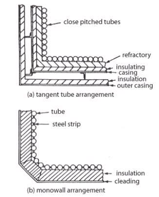
Fig 2.
Tangential and monowall arrangement
(Source: Seamanship International PC CD-ROM Engineering Knowledge)
In the tangent tube arrangement closely pitched tubes are backed by refractory, insulation and the boiler casing. In the monowall or membrane wall arrangement the tubes have a steel strip welded between them to form a completely gas-tight enclosure. Only a layer of insulation and cladding is required on the outside of this construction.
The monowall construction eliminates the problems of refractory and expanded joints. However, in the event of tube failure, a welded repair must be carried out. Alternatively the tube can be plugged at either end, but refractory materials must be placed over the failed tube to protect the insulation behind it. With tangent tube construction a failed tube can be plugged and the boiler operated normally without further attention.
Sometimes it is difficult to find the failed tube, in an exhaust gas boiler with closely fitted finned tubes for example, a method, which has found success, is ultrasonic detection.
Equipment required is a microphone pickup, connected to an oscilloscope.
• Pressurise the tube stack and headers with air.
• Enter the gas space with the microphone pick up.
• Go round the tube stack with the microphone.
• The maximum air hiss will give the maximum deflection on the oscilloscope.
• The leaking tube will be in that area.
Temporary Repairs To Membrane Or Monowalls At Sea (Ships’ Personnel)
The method of tube repair used in an emergency at sea would depend principally on whether a competent welder and machine are available. If not, the suitable plugs or expandable blind nipples for each of the failed tubes, should be available and also a supply of protective refractory to prevent subsequent burning through of the casing in way of the blanked-off tube.
(a) Welded repairs:
Welded repairs are usually of a patch nature and have the advantage that as the tube remains in use it is not necessary to protect it with refractory. A butt welded patch is preferable, but as this, and also any internally fitted patch, are liable, in the hands of an inexperienced welder, to result in weld splatter entering the tube bore, it is safer for a quick temporary repair to rely on an external fillet welded patch. For repairs of this nature the defective part of the failed tube is cut back to sound material and then a patch piece, preferably cut from a tube having bore equal to the outside diameter of the failed tube, is filet welded over the removed section of the failed tube – the overlap being kept small to prevent subsequent overheating when in service. Subject to a satisfactory hydraulic test on completion such a repair should allow the vessel to reach a port where permanent repairs can be effected (see below).

Fig 3.
Permanent welded repair
(Source: Seamanship International PC CD-ROM Engineering Knowledge)
(b) Mechanical repairs:
If a welded repair is impracticable the tube may be plugged at both ends providing the tube is subsequently protected by refractory to prevent local burning of tubes and possible the boiler casing.
Various mechanical plugging methods have been devised by the boiler designers, but lack of internal access and the high temperatures appertaining at shut down can make this an extremely unpleasant and/or lengthy operation. Two methods are described below:

Fig 4.
Permanent Mechanical repair
(Source: Seamanship International PC CD-ROM Engineering Knowledge)
Method 1. Windows are cut in the tube about 62mm from its extremities through which wires with taper plugs attached can be pulled the taper plugs having been inserted into the headers via the inspection doors. The plugs are pulled into position through pieces inserted across the windows, and are then pulled up solids by nuts.
After both ends of the tube have been plugged in this manner the whole length of the defective tube and the boiler casing behind it are shielded from the furnace heat during subsequent steaming by a thick shield of plastic refractory.
Method 2. Again windows are cut at each end of the tube through which blind nipples are inserted and subsequently expanded.
It will be appreciated that in this method boiler pressure tends to blow the plugs out whereas in Method 1 boiler pressure tightens the plugs in the hole. It is important to ensure therefore that with this method the expander rollers project down the bore of the nipple beyond the header or drum thickness so that an internal anti blow-out ‘collar’ is formed on the nipple during expanding; as a double precaution special ‘stepped’ roller can be used to form this collar.
As in Method 1, the whole length of the failed tube has subsequently to be shielded from the furnace heat.
Repairs To Membrane Or Monowalls In Port
The type of repair whether accepted as permanent or semi-permanent will depend largely on the availability of welders skilled in this type of work.
Inserting a new section
The obvious and most straightforward permanent repair consists of cutting out the defective length of tube along with part of its adjoining membranes and butt welding in a new section. This repair entails the services of skilled welders, the removal of casing and refractory in way of the repair, and accurate weld preparation.

Fig 5.
Insert repair
(Source: Seamanship International PC CD-ROM Engineering Knowledge)
It is important to note that unless welders skilled in the type of repair are available, the surveyor should insist that the welders being employed do a preliminary procedure test to his satisfaction.
Fish mouth tube replacement method

Fig 6.
Fish mount tube replacement method
(Source: Seamanship International PC CD-ROM Engineering Knowledge)
This method, when carefully executed, is also acceptable as a permanent repair and has the advantage that as all welding is done from the furnace it is not necessary to disturb the boiler casing and refractory.
The defective part of the tube along with part of its adjoining membranes are burnt out, as in the previous method. The replacement piece of tube is prepared with its top and bottom ends cut off at 45° to give access when the replacement is in position for welding, from the furnace, the rear part of the two circumferential butt welds.
When these rear parts of the circumferential welds have been satisfactory completed, wedge-shaped pieces of tube are welded into the two windows, and the circumferential butt weld then complete working from the outside. The membranes are subsequently closed by welding as in the previous method.
The configuration of the wedge pieces can be varied to suit tube diameter and access required and, if necessary, backing rings may be used.
The loose ring method

Fig 7.
Loose ring method
(Source: Seamanship International PC CD-ROM Engineering Knowledge)
In ports where it is doubtful whether the experience of the welders justifies their employment on the previous two methods of repair, it is possible by this ‘loose ring’ method, to make an acceptable repair of a semi-permanent nature using down hand welding.
In this method access has to be made all around the tube and loose rings with cupped upper surfaces are slid into position in way of the butts to be welded, so that an inexperienced welder has a better chance of making a butt cum fillet joint. In all other aspects the repair is as in the previous two cases.
In view of the extra metal thickness in way of the rings and possible build up of weld metal this repair could subsequently be the subject of overheating in service, and on that account the repair should only be regarded as semi-permanent.
Testing
On completion of any of the foregoing repairs whether temporary or permanent, the boiler should be subjected to a working pressure hydraulic test. In the case of the repairs effected in port the welds should be crack detected and, if possible, X-ray detection equipment should be used.
REFERENCE
1. Leslie Jackson & Thomas D Morton Reed’s General engineering knowledge for marine engineers (2002) Thomas Reed, pgs 89 – 136
2. Leslie Jackson & Thomas D Morton, Reed’s Motor engineering knowledge for marine engineers (2002) Thomas Reed, pgs 178 – 198
3. Seamanship International PC CD-ROM (2004) Engineering knowledge
4. www.marineengineering.co.uk
5. www.marinediesels.info