DIESEL ENGINE SCAVENGE FIRE

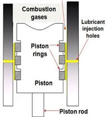
INTRODUCTION:

For any fire to begin, the fire tringle needs to be completed. To complete a fire tringle there must be present a combustible material, oxygen or air to support combustion and a source of heat at a temperature high enough to start combustion.

Source: www.marinediesels.info

In the case of scavenge fires:
 the combustible material is oil. The oil can be cylinder oil which has drained down from the cylinder spaces, or crankcase oil carried upwards on the piston rod because of a faulty stuffing box. In some cases the cylinder oil residues may also contain fuel oil. The fuel may come from defective injectors, injectors with incorrect pressure setting, fuel particles striking the cylinders and other similar causes.
 The oxygen necessary for combustion comes from the scavenge air which is in plentiful supply for the operation of the engines.
 The source of heat for ignition comes from piston blow-by, slow ignition and afterburning, or excessive exhaust back pressure, which causes a blowback through the scavenge ports.

• A scavenge fire can cause serious damage to the piston rod diaphragm gland as well as leading to possible distortion of the air box and cracking of the liner. Tie rod tension will almost certainly be affected.
• The worst case scenario for a scavenge fire is it leading to a crankcase explosion
• The fire may also spread outside the scavenge box due to relief doors leaking or oil deposits on the hot casing igniting. For these reasons a scavenge fire should be dealt with as quickly as possible.

INDICATION

 Loss in power and irregular running of the engine,
 High exhaust temperatures of corresponding units,
 High local temperature in scavenge trunk,
 Surging of turbocharger,
 Sparks and smoke emitted from scavenge drains.
 External indications will be given by a smoky exhaust and the discharge of sooty smuts or carbon particles.
 If the scavenge trunk is oily the fire may spread back-from the space around or adjacent to the cylinders where the fire started and will show itself as very hot spots or areas of the scavenge trunk surfaces.
 In ships where the engine room is designed as UMS, temperature sensors are fitted at critical points within the scavenge spaces. So, activation would cause automatic slow down of the engine.

ACTION TO BE TAKEN WHEN SCAVENGE FIRE OCCURRED

 In the event of scavenge fire the engine must be put to dead slow ahead as soon as possible and the fuel must be taken off the cylinders affected by the fire or preferably stopped.
 The turning gear should be put in and the engine continuously turned with increased cylinder oil to prevent seizure (jam).
 All scavenge drains must be shut to prevent the discharge of sparks and burning oil from the drains into the engine room.
 Air supply should be cut off by enclosing the turbocharger inlets, for mechanically operated exhaust valves the gas side should also be operated, (hydraulically operated exhaust valves will self close after a few minutes).

For a minor scavenge fire:
–  A minor fire may shortly burn out without damage, and conditions will gradually return to normal. The affected units should be run on reduced power until inspection of the scavenge trunking and overhaul of the cylinder and piston can be carried out at the earliest safe opportunity.
–  Once navigational circumstances allow it, the engine should be stopped and the whole of the scavenge trunk examined and any oil residues found round other cylinders removed.
–  The actual cause of the initiation of the fire should be investigated

For a major scavenge fire:

–  If the scavenge fire is of a more major nature, if there is a risk of the fire extending or if the scavenge trunk is adjacent to the crankcase with risk of a hot spot developing it sometimes becomes necessary to stop the engine.
–  Normal cooling is maintained, and the turning gear engaged and operated. Fire extinguishing medium should be applied through fittings in the scavenge trunk: these may inject carbon dioxide, dry powder or smothering steam.

 The fire is then extinguished before it can spread to surfaces of the scavenge trunk where it may cause the paint to start burning if special non inflammable paint has not been used.
 Boundary cooling of the scavenge trunk may be necessary. Keep clear of scavenge relief valves, and do not open up for inspection until the engine has cooled down.

After extinguishing scavenge fire:
 After extinguishing the fire and cooling down, the scavenge trunking and scavenge ports should be cleaned and the trunking together with cylinder liner and water seals, piston, piston rings, piston skirt, piston rod and gland must be inspected.
 Heat causes distortion and therefore checks for binding of piston rod in stuffing box and piston in liner must be carried out.
 Tightness of tie bolts should be checked before restarting the engine.
 Inspect reed valves if fitted, and scavenge relief valve springs.
 Fire extinguishers should be recharged at the first opportunity and faults diagnosed as having caused the fire must be rectified.

SAFETY FITTING

  1. Scavenge belt relief door
  2. Fire Fighting Media

1. SCAVENGE BELT RELIEF DOOR:

Scavenge belt relief door Fitted to both ends of the scavenge belt and set to lift slightly above the maximum normal working scavenge air pressure.

2.  FIRE FIGHTING MEDIA
 Carbon dioxide- will put out a fire but supply is limited. Susceptible to loss if dampers do not effective prevent air flow
 Water spray- perhaps the ideal solution giving quick effective cooling effect to the fire.
 Dry powder- will cover the burning carbon and oil but is messy. As the fire may still smoulder below the powder care must be taken when the scavenge doors are removed as the powder layer may be blown away.
 Steam smothering-plentiful and effective


Source: www.marinediesels.info

PREVENTION

 Good maintenance and correct adjustment must be carried out
 Scavenge trunking must be periodically inspected and cleaned and any buildup of contamination noted and remedied.
 The drain pockets should also be cleaned regularly to remove the thicker carbonized oil sludges which do not drain down so easily and which are a common cause of choked drain pipes
 Scavenge drains should be blown regularly and any passage of oil from them noted.
 The piston rings must be properly maintained and lubricated adequately so that ring blow-by is prevented.
 At the same time one must guard against excess cylinder oil usage.
 With timed cylinder oil injection the timing should be periodically checked.
 Scavenge ports must be kept cleared
 The piston-rod packing rings and scraper rings should also be regularly adjusted so that oil is prevented from entering the scavenge space because of butted ring segments.
 This may and does occur irrespective of the positive pressure difference between the scavenge trunk and the crankcase space.
 Fuel injection equipment must be kept in good condition, timed correctly, and the mean indicated pressure in each cylinder must also be carefully balanced so that individual cylinders are not overloaded.
 If cylinder liner wear is up to maximum limits the possibility of scavenge fires will not be materially reduced until the liners are renewed

REFERENCES:
1. www.marineengineering.co.uk
2. The Running and Maintenance of Marine Machinery – Cowley
3. Reeds Marine Engineering Series, Vol. 12 – Motor Engineering Knowledge for Marine Engineers
4. Lamb’s Question and Answers on Marine Diesel Engines – S. Christensen
5. Diesel Engines – A J Wharton
6. www.marinediesels.info

LATEST DEVELOPMENT ON EU-MRV

ships_pollution
Monitoring Reporting & Verification (MRV) is a standardised method to produce an accurate CO2 emissions inventory, through the quantification of CO2 emissions. The key principles of the scheme are to generate robust results using a lean approach considering parameters which are already monitored during normal operations.
It is advocated as a way of monitoring a ship’s fuel consumption and its operational energy efficiency performance.

MRV is still under discussion in IMO and they will come up with a decision in next MEPC. The new EU Regulation 2015/757 came into force on 1 July 2015 and operating from 2018.

There is a MEPC Working Group active on the subject:
 A corresponding working group and pilot testing of various schemes are encouraged.
 Work has significantly progressed and is likely to finalise in 2016.


IMO MRV main elements:
 Data collection
 Data verification
 Data submission to a central database.

IMO MRV status:

  • Applicable to ships >5000 GT
  • Annual reporting
  • IMO number for ship identification
  • Guidelines will be developed to deal with various aspects.
  • Registered owner is responsible for submission of data to Administration
  • Administration responsible for verification (can be delegated to ROs).
  • A Statement of Compliance will be issued to ship annually
  • PSC will examine SFC for enforcement
  • Responsibility of reporting remains with ship
  • Transport work and other data to be decided later.

The Regulation follows the European Parliament’s Resolution of 5th February 2014, which called upon the Commission and Member States to set a binding target of reducing domestic greenhouse gas emissions by at least 40% compared with levels observed in 1990.

CO2 emissions from international shipping, related to the EU alone, increased by 48% between 1990 and 2007. However, as yet international maritime shipping remains the only means of transportation which has not been included in Community proposals to reduce greenhouse gas emissions.

In light of the developing scientific understanding of the impact of maritime transport on the global climate, it has been decided that this should be assessed regularly and that the European Commission should consider implementing policies and measures to reduce both CO2 emissions and other kinds of emissions from vessels in future. According to data provided by the IMO, the energy consumption and emissions of ships could be reduced by up to 75% by applying operational measures and implementing technologies which already exist. It is believed that the best option for reducing CO2 emissions from shipping is to set up a system for monitoring, reporting and verification (MRV) of CO2 emissions based on the fuel consumption of ships. The MRV system is set out in the form of a Regulation due to the complex and highly technical nature of the provisions introduced, the need for uniform rules applicable throughout the European Union, and to facilitate implementation of these proposals throughout the European Union.

Regulations for MRV
1. Article 4: Article 4 of the Regulation sets out ‘common principles’ for monitoring and reporting. For each ship with a gross tonnage above 5000GT, ship owners must provide a complete report covering CO2 emissions from the combustion of fuels whilst ships are at sea as well as at berth. It is important to apply appropriate measures to prevent any gaps in the data – the whole period must be covered (Article 4(2)).

The data produced must also be accurate – the burden is on the ship owner to identify the source of any inaccuracies and prevent them (Article 4(5)).

Monitoring and reporting must also be consistent. The same monitoring methods and data sets should be used so that the data acquired can be compared overtime and any increase or decrease in emissions can be accurately monitored (Article 4(3)).

The monitoring data itself must be collected and documented in a transparent manner. This will enable any independent verifier to reproduce the methods used to determine the vessel’s CO2 emissions (Article 4(4)).
2.  Article 5: Article 5 of the Regulation sets out specific methods for monitoring and reporting vessel emissions, as well as other relevant information, by reference to Annexes I and II. By Article 5(1) any of the methods set out in the Annexes may be used to determine CO2 emissions and other relevant information.

Methods for determining CO2 Emissions
It is recommended that Members look into the detailed provisions of Annexes I and II themselves. However, we include a brief summary of the key points below. Four methods for determining CO2 emissions are given in the Regulation, as set out in the following formulae: (from Annex I):
Fuel consumption x emission factor

For the emission factor, default values shall be used unless the company decides to use the fuel quality data set out in the bunker delivery note for that fuel.

For the actual consumption of fuel, Annex I provides the following approved methods:

Fig: EU-MRV scheme overview (Source: LR)

Method A: Bunker Delivery Notes and Periodic Stock-Takes of Fuel Tanks
This method is based on the quantity and type of fuel as defined in the bunker delivery notes, compared with information gained from periodic stock-takes. The fuel at the beginning of the monitoring period, plus deliveries, minus fuel available at the end of the period and de-bunkered fuel will indicate how much fuel has been consumed.
Fuel tank readings must be carried out by methods such as automated systems, soundings and dip tapes. Whichever method is used, it must be specified in the monitoring plan.

Method B: Bunker Fuel Tank Monitoring On-Board
This method is based on fuel tank readings for all the fuel tanks on board. The readings must take place daily when the ship is at sea and each time the ship is bunkering or de-bunkering. The cumulative variations of the fuel tank level between two readings will constitute the fuel consumed over the period, which might be the time between two port calls or time spent within a port.
As above, the method of taking fuel tank readings must be an ‘appropriate method’ and be specified in the monitoring plan.

Method C: Flow Meters for Applicable Combustion Processes
This method is based on measured fuel flows on board. The data from all the flow meters linked to relevant emission sources will be combined to determine all fuel consumption for a specific period. Again, the period might be the time between two port calls or time spent within a port.

Method D: Direct Emissions Measurement
This method may be used for voyages within the scope of the Regulation and emissions occurring in ports located in a Member State’s jurisdiction. For ships on which reporting is based on this method, fuel consumption will be calculated using measured CO2 emissions and the applicable emission factor of the relevant fuels.

This method is based on the determination of CO2 emission flows in exhaust gas stacks (funnels) by multiplying the CO2 concentration of exhaust gas by the exhaust gas flow.

Monitoring Plan
Under Article 6(1), by 31st August 2017 a monitoring plan must be submitted to the verifiers which indicates the method chosen to monitor and report emissions and other relevant information. Each ‘company’ must submit a separate plan for each ship to which the Regulation applies. Should ships fall within this Regulation only after the 31st August 2017, the plan must be submitted without undue delay (Article 6(2)).

The monitoring plan is meant to be a complete, transparent documentation of the monitoring methodology for the specific ship. It must contain:
a) the identification and type of ship (including its name, IMO number, port of registry and owners’ name);
b) contact details for the ‘company’ responsible for monitoring and reporting;
c) a description of the emission sources on board (the main engines, auxiliary engines, gas turbines, boilers, inert gas generators) and the fuel types used;
d) a description of procedures, systems and responsibilities used to update the list of emission sources;
e) a description of procedures used to monitor the completeness of the list of voyages;
f) a description of the procedures for monitoring fuel consumption, emission factors for each fuel type used (including how these were calculated in the case of alternative fuels);
g) a description of the procedures used to determine activity data per voyage, a description of the method to be used to determine surrogate data (in the case of data gaps); and
h) a revision record sheet to show any revisions which have been made.
As can be seen from the above this is a comprehensive document and therefore templates will be provided in order to streamline and standardise this process. The form these will take is as yet undecided, but it is indicated by Article 6(4) that these will be determined by means of implementing acts in the near future.

Under Article 7, the company is required to modify the monitoring plan in certain situations:
a) if there is a change of company (i.e. another party takes on that role in relation to the vessel);
b) if there are new emission sources or fuels are used which are not yet referred to in the monitoring plan;
c) where there is a change in the availability of data (e.g. because new methods are being used to collect it);
d) where data resulting from previously used methods has been found to be incorrect; or
e) if the monitoring plan does not conform to the above requirements. (If the monitoring plan does not conform, the verifier will request that the company modifies the plan. In other circumstances, the company must notify any planned modifications to the verifiers without undue delay.)

Having chosen a method and prepared a monitoring plan, companies must then monitor emissions for each ship both on a per-voyage & annual basis (Article 8). Where emissions are monitored on a per-voyage basis, Article 9 stipulates that the following information must be monitored:
a) the ports of departure and arrival (including date and time of departure/arrival);
b) the total amount and emission factor for each type of fuel consumed;
c) CO2 emitted;
d) distance travelled;
e) time spent at sea;
f) cargo carried; and
g) transport work.

However, ships are exempted from the need to monitor emissions on a per-voyage basis if all the ship’s voyages either start or end at a port under the jurisdiction of a Member State or the shipper forms more than 300 voyages in a year.

Where emissions are monitored on an annual basis, for each ship the company must monitor:
a) the amount and emission factor for each type of fuel consumed in total;
b) the total aggregated CO2 emitted;
c) the aggregated CO2 emissions from all voyages:
–  between ports under a Member State’s jurisdiction,
–  which departed from ports under a Member State’s jurisdiction,
–  to ports under a Member State’s jurisdiction, and
d) any CO2 emissions which occurred at berth within ports under a Member State’s jurisdiction.
e) In addition, the total distance travelled, total time spent at sea, total transport work and average energy efficiency of the vessel must be monitored.

The schedule for implementation for EU-MRV
Reporting periods are defined as a calendar year. For voyages starting and ending in two different calendar years, the monitoring and reporting data is to be accounted under the first calendar year.
To simplify the preparation of monitoring plans and reporting requirements, electronic templates will be provided by the European Commission (EC). The following timescales have been set as part of the regulation:
Preparation and adoption of supporting technical legislation in 2015/2016 including broad stakeholder and expert involvement
– Accreditation of verifiers in 2017
– 31st August 2017 – Monitoring plan to be prepared and submitted for approval by an accredited verifier
– 1st January 2018 – Commence per-voyage and annual monitoring
– 2019 onwards – By 30th April each year, submit a verified emission report to the EC and relevant flag state
– 30th June 2019 onwards – Ships will need to carry a valid document of compliance relating to the relevant reporting period.
– 30th June each year – the EC will make each ship’s emissions reports publicly available including information specific to that ship, its fuel consumption, CO2 emissions, technical efficiency (EEDI or EIV as appropriate) along with other parameters.

Source: The Japan P&I Club and Lloyd’s Register

MARPOL ANNEX VI CHAPTER 1-3: “AIR POLLUTION AND GHG EMISSIONS FROM INTERNATIONAL SHIPPING

CYLINDER LUBRICATION SYSTEM

Cylinder lubrication in a low-speed main propulsion diesel engine:

Cylinder lubrication For marine diesel engines operating on residual fuels containing sulphur, cylinder lubrication must generally serve the following purposes:
■ Create and maintain an oil film to prevent metal to metal contact between the cylinder liner and piston rings.
■ Neutralise sulphuric acid in order to control corrosion.
■ Clean the cylinder liner, and particularly the piston ring pack, to prevent malfunction and damage caused by combustion and neutralisation residues.


Cylinder lubricating oil for a low-speed main propulsion diesel engine is admitted to each cylinder during the compression stroke. Cylinder lubricating oil, for lubricating the piston rings and the liner, has to be admitted when the piston, piston rings and the liner are in cool condition and the piston is moving upward so that oil can be retained on the piston rings and sprayed by the piston rings on the liner walls. This is only possible during the compression stroke. Otherwise, the piston is hot and if the lubricating oil is sprayed on it, it will evaporate very fast and will not carry out any work of lubrication. At the same time, if lubricating oil is injected during the expansion stroke, i.e. when the piston is moving downwards, it will have a scrapping effect rather than lubrication.

Cylinder Lubrication in four-stroke trunk piston engine:

In four-stroke trunk piston engines, there are a number of different methods for lubricating the cylinder liners and piston rings, depending on engine size and make:
■ Splash from the revolving crankshaft
■ “Inner lubrication”, where the oil is supplied from the piston side
■ “Outer lubrication”, where the oil is supplied by an external, separate cylinder lubricating device from the cylinder liner side.
In a four-stroke trunk piston engine, the cylinder lubricating oil is identical to the engine system oil used for bearing lubrication and cooling purposes.
A small amount of the cylinder lubricating oil by-passes the piston rings and ends up in the combustion space,
where it is “consumed”. However, the piston in a four-stroke trunk piston engine has an oil scraper ring that scrapes most of the oil supplied to the cylinder liner back to the engine’s oil pan, from where it is drained, cleaned and recycled.
Normally, a large, modern, well maintained four-stroke trunk piston diesel

engine will consume some 0.3 to 0.5 g/kWh of lubricating oil.

Type of Oil Used in Cylinder Lubricating System

  • The cylinder lubricant must be of a higher viscosity so that it can form a good lubricating film between the liner and the piston rings.
  • It must also withstand the heat variations in the combustion area and must deal with the combustion products.
  • Under normal running conditions this oil will typically be an alkaline cylinder lubricating oil of SAE 50 viscosity.
  • The alkalinity is indicated by the TBN (Total Base Number ) rating of the lubricant. The TBN value most suitable for the cylinder lubricating oil depends largely on the sulphur content of the fuel used. Typical values for sulphur content of 0.5 to 1% may be between 20 to 25 TBN. For sulphur content over 1.5% the TBN number may be 70 or higher.

Using the Correct Feed Rate for Cylinder Lubrication

Once the correct lubricating oil is chosen the correct feed rate must be established in accordance with the engine builder’s recommendations.

  • The feed rate has a critical effect on good engine operation apart from the question of oil consumption. With a too low feed rate the danger of the oil film breaking down causing blow by or additional wear is increased.
  • Too high a feed rate is a waste of lubricant and money. The correct feed rate will allow the formation of the lubricating film between the liner and the rings and will give maximum protection at the piston reversal points.

2

The cylinder oil consumption burette is a useful means of checking the oil consumption of individual lubricator boxes to help ensure that the oil is distributed across the boxes as intended.

The volume between the two internal discs is 1/2 litres. Given the temperature density characteristics of the oil, the actual mass of the oil during
its use in engine calibration can be calculated from the oil temperature. Calibration time lies typically between 3 10 minutes depending on the oil consumption rates and the speed/power of the engine, (if the oil feed drive is speed/power dependent).

In slow speed operation, the use of heavy fuel oil with high sulphur content makes the job of the cylinder lubricant very difficult. Even high alkalinity oils cannot hope to neutralise all the sulphuric acids which are produced during combustion.

Effect of Under Lubrication and Over Lubrication of Cylinder:

A correct viscosity is important in order to ensure the spreadability of the cylinder oil, and the applied feed rate and injected amount of oil per stroke are key factors in the delicate balance between under- lubrication and over- lubrication:

■ Under-lubrication
If too little cylinder oil is supplied, starvation will occur which might result in corrosion, accumulated contamination from unburned fuel and combustion residues, and in the worst case, metal to metal contact, known as “scuffing”.
■ Over-lubrication
If too much cylinder oil is supplied, the loss of fresh, unused oil in the scavenge ports
will be high, and the piston rings might be prevented from moving (rotating) in their grooves by the so called
“hydraulic lock”. Furthermore, the cylinder liner running surface structure might over time become closed and smooth like a mirror, and will no longer be able to retain the lubricating oil. This is sometimes called “chemical bore polish”, and when alkaline deposit build-up on the piston top land from excessive cylinder oil is in contact with the cylinder liner running surface, it can cause what is sometimes called “mechanical bore polish”. All of these phenomena might eventually result in scuffing.

Acid Condensation in the combustion chamber

The cooling system must be operated so that the piston and cylinder liner temperature is not dropped below the temperature at which the Sulphuric acid may condense on the cylinder liner.

Acid condensation depends on:

• the engine combustion pressure
• the liner temperature
• the concentration of the sulphur oxides
• the humidity of the intake air.

So, to help the lubricant in neutralising the acid, the engineer must ensure that the temperature of the scavenge air should be maintained in accordance with the manufacturers’ recommendation. Too low a scavenge air temperature will result in condensation with the risk of moisture entering the cylinders; too high a scavenge air temperature will adversely affect the combustion characteristics of the engine.

Engine Runing-in

Critical to this lubrication area is the way the engine has been run in at commissioning. A good run in procedure will create a good wear in of the cylinder liner and piston ring. A good gas seal is obtained between them whereby a thin oil film provides reliable and effective lubrication.

The period and method of running in should be decided upon in accordance with the engine manufacturer’s recommendation. Even if only new rings have been fitted the running in procedures should be as near as possible to that recommended for new engines.

The running in recommendation may specify the use of a particular type of lubricant and the feed rate should be high. After running in, the normal cylinder oil will be used and the feed rate gradually adjusted until the recommended feed rate is reached.

So, the cylinder lubricating oil must create a lubricating film between the piston ring and the liner, and must maintain effective lubrication. It must also combat corrosive wear. The use of the correct lubricant and the correct feed rate for the engine load will help to achieve the best result from the lubricant.

Lubrication Of Medium Speed Trunk Piston Engine

3
In medium speed diesel the cylinder is open to the crank case. This means that contamination of the crank case oil by combustion products requires the oil to be different in character to that which may be used in a slow speed engine. Generally, the lubricant must:

* create and maintain effective lubrication between moving components under high mechanical and thermal loads;

* transport solid contaminants from the cylinder to the cleaning devices, such as filters and centrifuges;

* withstand heat; fight contamination, corrosion and wear; resist oxidation and thermal breakdown; keep the engine clean.

References:
1.  www.marinediesels.info
2.  The Running and Maintenance of Marine Machinery – Cowley
3.  Reeds Marine Engineering Series, Vol. 12 – Motor Engineering Knowledge for Marine Engineers
4.  Lamb’s Question and Answers on Marine Diesel Engines – S. Christensen
5.  Principles and Practice of Marine Diesel Engines – Sanyal
6.  www.wartsila.com

THE TRIPLE E SHIP’S CONCEPT FOR MORE ENERGY EFFICIENCY

triple-e-ship-shape
Image Credit: www.maersk.com

The Triple E Ships can be more energy efficient and more environment friendly. Triple-E (EEE) stands for Energy efficient, Economy of scale and Environmentally improved vessel:

Energy Efficiency:
Triple-E ships are designed and optimised for lower speeds. The unique hull design, energy-efficient engine and system that uses exhaust gas to produce extra energy to help propel the ship, make the Triple-E unmatched in energy efficiency.

Economy of Scale:
The Triple-E ships break the world record in container ship capacity without requiring more engine power. This design takes economy of scale to a new level.

Environmentally Improved:
The Triple- E ships, with their unique design features for slower speeds and maximum efficiency, emit 50% less CO2 per container moved. (as claimed by Mearsk Line Triple-E project).

Grams of emitted CO2 transporting 1 ton of cargo 1 km:
Triple-E Container Ship: 3g
Conventional railway: 18g
Truck or Lorry on road: 47g
Aeroplane or by air: 560g

triple-e-enviroment
Source: www.maersk.com

The Triple E Container Ships:

The vessels will be the most energy efficient. They will have the lowest carbon dioxide (CO2) footprint by emitting 50% less CO2 per container moved when compared to the most efficient container vessel available currently. Optimised design will allow the vessel to cruise with the maximum possible load at speeds prevailing in the industry.

The waste heat recovery system will capture the exhaust gas from the engine and use it to run the turbine to produce mechanical energy, which in turn, will be used to run a generator. It will trim down fuel consumption and CO2 emission by about 9%.
environment-3
Source: www.maersk.com

Propulsion System:

The Triple-E class vessel will have a twin skeg propulsion system, with two slow running ultra-long stroke engines. Each engine will drive a separate propeller. Each engine will produce 43,000hp and weigh 910t with a specific fuel oil consumption (SFOC) will 168g/kWh. Each of the two propellers will be of 9.8m diameter and have four blades. The smaller the number of blades, the less the resistance will be, while the larger diameter propellers will produce more pushing power. The two engines and two propellers combination will generate further savings of 4% energy when compared to a combination of one engine and one propeller.
Moreover, the triple-E ship’s will be fitted with two Shaft Generator Motors with a rated capacity of 3MW each. The motors will act as variable power generation units which will save more energy.

References:
1. www.maersk.com
2. www.ship-technology.com

NOVEC 1230- THE NEXT GENERATION OF HALON AND CO2

fm-novec_system_3
Image Credit: www.protec.co.uk

Novec 1230, C6F12O, (3M Novec 1230) fluid is a low global warming potential Halon replacement for use as a gaseous fire suppression agent. Novec 1230 is manufactured by 3M. This Fire Protection Fluid is an advanced, “next-generation” halon and CO2 replacement, offering a number of important advantages over other clean agents and CO2 in marine applications. With zero ozone depletion potential, short atmospheric lifetime and a global warming potential of 1, Novec 1230 fluid has proven to be the first chemical halon replacement to offer a viable, long-term, sustainable solution for marine fire protection.


The product is based on a proprietary chemistry from 3M. Its low acute toxicity, combined with high extinguishing efficiency, gives Novec 1230 fluid the widest margin of safety among all other chemical clean agents and CO2 – even at relatively high extinguishing concentrations. This makes Novec 1230 fluid ideal for occupied spaces,
including engine and pump rooms, paint lockers and communication and control centers where personnel may be exposed to the agent upon system discharge. Novec 1230 fluid vaporizes rapidly during discharge, and it is non-corrosive and non-conductive, so it will not harm delicate electronics, radar, navigation and other equipment. And, unlike foams and powders, it leaves no residue to clean up, which means that operations can continue without interruption.

Total Flooding Systems_Novec1230
Image Credit: safety1021.rssing.com

Fig: Novec 1230 total flooding system in engine room.

Novec 1230 fluid is a high molecular weight material, compared with the first generation halocarbon clean agents. The product has a heat of vaporization of 88.1 kJ/kg and low vapor pressure. Although it is a liquid at room temperature it gasifies immediately after being discharged in a total flooding system.

The product is ideal for use in total flooding applications, localized flooding systems, directional spray type applications and may be used in portable extinguishers for specialized applications. But in addition to the conventional methods of super-pressurization using nitrogen, Novec 1230 fluid also lends itself for use in pump applications because it is a liquid.

It has been used as a full-immersion fluid in a proof of concept data center cooling system by Intel and SGI[2]

Chemically, it is a fluorinated ketone with the systematic name 1,1,1,2,2,4,5,5,5-nonafluoro-4-(trifluoromethyl)-3-pentanone and the structural formula CF3CF2C(=O)CF(CF3)2, a fully fluorinated analog of ethyl isopropyl ketone.

The detail information of 3M Novec 1230 can be found by clicking the below links:
Click to access 3m-novec-1230-fire-protection-fluid-marine-application.pdf
Click to access enhanced-fire-protection-for-marine-applications.pdf

Source: www.3m.com

ON THE WAY OF INNOVATION- THE MOST ENERGY EFFICIENT CAR!

123
Impressive news from the new Prototype CNG category late yesterday afternoon: team Microjoule-La Joliverie pulled off a 2,521km/litre equivalent first attempt (imagine driving from Rotterdam to Palermo on one litre). New category, new benchmark.

The first UrbanConcept challenge started this morning. First on track was Louis Delage School from France with their gasoline car, pulling off 476km/litre equivalent to lead their category and set a new record. French Team IUT GMP Valenciennes from France have set a record of 1,323km/l in the Prototype diesel category.


DTU Roadrunners soon rode triumphantly to the top of the UrbanConcept ethanol category with 557km/l equivalent. After fire damaged their car two days ago, and with 200 hours of combined teamwork under their belts, the result was just 42km/l short of their 2014 winning best.

In Prototype gasoline, team TED from France swept into the lead, above Remmi-Team, with 2,308km/l.

The car’s internal combustion engine uses a high-pressure injection system to deliver a fine spray of gasoline and air into the combustion chamber about 25 times per second. The size of the spray nozzles and the duration of each jet (just 7 milliseconds) are critical to the engine’s performance.

The same principle applies when using compressed natural gas, except natural gas moves much more freely than liquid gasoline. The challenge for CNG teams this year is to hit just the right balance between the size of the spray nozzles and the timing of the jets. It also means fine-tuning their electrical systems. Gas purity also has a big impact on performance.

Shell Press Release.
Please follow the link for details:
http://www.shell.com/global/environment-society/ecomarathon/events/europe/2015-highlights/innovation-is-all.html