Category Archives: Maritime Regulations

Energy Efficiency Rules for Onboard Seafarers

This learning material is prepared to help seafarers with sailing experience onboard ships clearly understand the latest international and regional regulations. It explains each rule with objectives, details, and practical examples so that by reading only, you can connect the regulations with daily shipboard work Continue reading

marpol convention

SUMMARY OF MARPOL AND SOLAS AMENDMENTS ENTERING INTO FORCE FROM 01 JANUARY 2020

MARPOL:

Annex VI 0.50% Sulphur Limit: The limit for sulphur in fuel oil used on board ships to be reduced to 0.50% m/m (mass by mass).

SOLAS:

Amendments to SOLAS regulations III/3 and III/20 to make mandatory the requirements for maintenance, thorough examination, operational testing, overhaul and repair of lifeboats and rescue boats, launching appliances and release gear.

Amendments to SOLAS regulation II-2/13 to extend the requirements for evacuation analysis to all passenger ships, not just RO-RO passenger ships.

Continue reading

marpol convention

IMO SULPHUR REGULATIONS 2020

The 2020 IMO global 0.50 percent fuel Sulphur Technical Note:

In less than a week time, From 1st January 2020, the maximum permissible global Sulphur content of marine fuels is going to be reduced from

3.5 % to 0.5% according to MARPOL Annex VI. Ships operating outside

Emission Control Areas (ECAs) will have three options to achieve compliance:

  1. By the use of exhaust gas abatement technology (‘scrubbers’), or
  2. By burning a fuel with maximum Sulphur content of 0.50%mass, or
  3. By burning LNG. To meet continuing legislation inside ECAs.

Continue reading

CHIEF ENGINEER RESPONSIBILITIES DURING BUNKERING OPERATION

(By Kamal Hossain, Chief Engineer)

Pollution prevention

    1. Pre-bunkering meeting should be held , quantity , grade and distribution plan to be drawn up.
    2. By considering of volume allowance is 10 ~ 15 % for expansion , all tanks to be filled up to 85 % maximum.
    3. Clear over flow tank , drain tank .
    4. Top up settling and service tanks.
    5. Clean filters and sight glass of bunker line.
    6. Keep level indicator, sounding gauge and pressure gauge good working order.
    7. Arrange quick communication between bunker point and control .
    8. Check scuppers plug condition.
    9. Keep cleaning materials and chemical near by bunker point.
    10. Alert oil pollution control team as per contingency plan.


  1. Exact reading of draught and list to calculate trim of the ship. Keep vessel up right as possible.
  2. All tanks to be sounded priorly.
  3. Check valve opening to correct tank and others shut.
  4. Predetermine the pumping rate and emergency stop signal with supply barge.
  5. Pumping slowly during first stage , check oil enter to correct tank , hose connection especially on the non-used side, then increase to predetermined pumping rate.
  6. Check sounding of filling tanks frequently , use ullage method.
  7. Regular check for oil trace from connections and ship side discharge . If any leak is found , stop bunker immediately.
  8. Essential to slow down when 80 % of total quantity and to be stopped at 85%.
  9. Let all valves open for some duration to expel the air from tank.
  10. Avoid spillage when connecting or disconnecting the hose.

U.S.C.G Regulations

  1. Bunker plan must be drawn up . All crew to be explained total bunker quantity , distribution plan , filling sequences. Engine room staffs to be assigned each and individual duties regarding bunker. This plan and assignments must be posted at bunker point.
  2. All bunker tanks must have vent pipes with flame trap head and spilled oil container of 1 Barrel Quantity to be placed near vent pipes.
  3. Chief Engineer must prepare necessary paper forms and to be signed prior to bunker as per procedures to regulations.

Fire Prevention

  1. Bunker oil flash point must not be less than 65’C under any circumstance as a rule.
  2. Ensure no oil leakage.
  3. No naked light or smoking is allowed in the vicinity.
  4. Keep fire stand-by watch with portable fire extinguishers.

How to minimize the shortage.

  1. Take exact reading of draughts and list to calculate trim of the ship. Keep vessel up right as possible.
  2. All tanks to be sounded . Calculate on board balance condition and plan the distribution.
  3. Avoid mixing the bunker from different origin.
  4. Check specifications of bunker , temperature , flash point , viscosity , specific gravity ,…. ect., according to delivery order.
  5. Take soundings of bunker barge using water finding paste .
  6. Record time of commence and completion , pumping rate .
  7. Take final soundings of total bunker by using water finding paste  , calculate receiving amount of bunker by using volume correction factor as per A.P.I  and gravity with exact temperature.
  8. Call bunker surveyor through agent for any dispute.

After bunker

  1. Take 3 sample bottle , one for ship , one for analysis and another for bunker supplier. All samples to be sealed ,with both ship and barge ‘s stamps , date , place and signs of Chief Engineer and supplier.
  2. Check delivery receipt , describing amount and specifications to be the same with delivery order. Then chopped and signed. At least 2 copies of receipt to be kept for ship. One for F.O report to Head Office and one for ship file.
  3. Log to be enter official and actual receipts. B.O.B at this moment to be mentioned. Inform bridge.
  4. Oil Record Book to be entered with correct code no., item no., date, place, exact time of commence and completion, added  and total quantity of tanks with number, and signed.

How to take sample and requirements.

  1. Sample must be taken by continuous dripping method . The sample to be drawn from bunker line by using of dripping probe or  drain valve crack open for dripping at oil pump out let from barge.
  2. Sample bottle is 1 ltr capacity. If tin container it must be 4 ltr capacity.
  3. Sample oil bottle is to be sealed in front of Chief Engineer or other witness.
  4. On the seal the following to be provided.
  5. Place and date of bunker sampling
  6. Method and place of drawn
  7. Name of barge
  8. Name of ship
  9. Quantity and grade
  10. Name of Chief Engineer and Supplier
  11. Signs of them
  12. Samples to be taken 3 bottle. One for ship , one for analysis and another for supplier.
  13. Sample should be kept on board not less than 30 days from date of bunker receiving or until the bunker is totally consumed.

Bad  Bunker

Bad bunker is caused when taking two different fuel oil within a specifications but a heavy sludge precipitation and not fit for further use. It may effect the Engine the following problems.

  1. High exhaust temperature
  2. Burning exhaust valve
  3. High combustion pressure
  4. Blow by and fire in scavenge
  5. High wear rate of engine parts
  6. Decrease performance
  7. Clogging of fuel system

How to minimize to receive bad bunker

  1. Order to standard marine fuel oil supplying contract
  2. Specifications must be complied with engine maker’s recommendations.
  3. Bunker may be refused if in doubt regarding specifications.
  4. Try not to mix bunker from different origin. Store in a tank having no oil remains.
  5. Proper sample to be drawn , sealed and taken.
  6. Sample to be analyzed by renown company.
  7. Sample to be kept on board till oil is totally consumed.
  8. Try not to burn as possible , before receiving lab report.

How to use bad bunker oil if  No-way

  1. Sludge dispersion chemical to be applied to banker storage D.B and settling tanks.
  2. Applied heating to storage D.B ,settling and daily service tanks at temperature well above its pour point for separation of water and other impurities. Frequent draining practice to be followed.
  3. Use double stage purification method with slow feed rate. ( Purifier & Clarifier in series operation ). Frequent Desludging process to be made. Cleaning of these centrifuges and their filters to be done more than normal routine.
  4. Chemicals to be added in daily service tanks to improve combustion.
  5. Filters in F.O system to be cleaned more than normal routine.
  6. Maximum permissible heating temperature to be applied to gain good viscosity control at visco-therm unit.
  7. In some case , raise the temperature of fuel and charge air temperature 5 ~ 10’C more , it may effective to avoid combustion delay and fuel knocking.
  8. While engine is running with bad fuel, the following factors to be keep close watch, and maintenance to be done:
  • Exhaust temperature
  • Cylinder and piston cooling temperatures
  • F.O line and end heater temperature
  • Visco-therm unit
  • Charge air temperature.
  • Turbocharger r.p.m
  • Multiply the turbocharger water washing practices.
  • Peak pressure indicator to be taken and check the engine condition.
  • Fuel injectors to be cleaned and pressure to be tested

 How to handle and maintain bunker oil

It is necessary to maintain and up grade the critical properties of bunker oil through the ship board process. These are consisting of the followings:

  • Sediments settling process
  • Filtering process
  • Centrifuging process
  • Mechanical process
  • Chemical process.

The procedures for the above process are as follows:

1. Bunkers of different origin are stored in separate D.B. tanks. Coarse filters in bunker line is passed by the bunker oil while bunkering.

2. Heating is applied to storage D.B. tank to keep bunker oil temperature well above pour point and below flash point

3. Detergent type chemical additives should be dosed into the storage D.B. tank to prevent too much sludge formation.

4. Then , transferred the oil by pump with coarse filter, to settling tanks, which are having adequate heating arrangement and designed with slope bottom to improve contaminant draining. In this tanks , oil is settled and applied heating. Gravitational separation of oil from water and other impurities may occur and frequent drainage of them can be done. Oil temperature in this stage is kept not more than 60’C practically.

5. After settling out some water and impurities for about 24 hrs or more, the oil is fed to the separators passing through coarse filters in each unit again.
Double stage separation method by using purifier and clarifier in series with heater is promoting separation effect. All the contaminants and water are separated off during these process and almost clean oil is led to daily service tank which is same designed and arrangements provided as settling tanks.

6. Some firms are making finishing touch process at this point which are include several filters, Ultrasonic or Mechanical Homogenizer and Emulsifiers.

7. At the daily service tanks, by applying heating and maintain oil temperature about 60’C practically gravitational separation occur again. Then some remaining water can be drained out if any. Chemical for combustion improver can be dosed. At this stage , the oil is well processed and ready for use.

8. For burning process, the oil is drawn by booster pump from daily service tank to closed mixing column via coarse filter. From there the circulating pump feed oil to end heater to give correct injection viscosity control by Visco-therm unit. piping from end heater to fuel pump and injectors are provided with heating arrangement, and heated oil is led to pass through back flush filter which having filtering capacity up to 1 micron particles.

SHIP CHARTER

F R Chowdhury

In shipping when a ship is hired it is always referred to as being on charter. The owner of the ship is still referred to as the owner and one who hires the ship or space thereof is referred to as the charterer. The instrument of agreement is known as the “charter party”, commonly called C/P. There are standard forms for different types of charter devised by various international trade associations and chambers of trade and commerce including the ICC, BIMCO and the Baltic Exchange. C/P is normally drawn by mutually (ship-owner and charterer or their agents) agreeing to various clauses of one of the specific forms with special conditions or exception/ exemption noted by lines. The coal, grain rice, timber, stone, ore, fertiliser, and other trades all have their own forms of charter-party. There are 3 conventional types of charter. They are:
1. Demise or Bare-boat charter
2. Time charter
3. Voyage charter

Demise or bare-boat charter:

as the name implies it is the charter in which the charterer hires the ship for a long period of time, mostly in newly built condition directly from the yard, and takes delivery of the ship with no crew, stores or bunkers. In other words the delivery of the ship is made in its bare state. The charterer employs his staff to man the vessel, puts on board stores, provision and spares as considered necessary, takes bunkers, finds cargo and employs the vessel. In most cases the insurance of the vessel may be also undertaken by the charterer. The charterer takes the responsibility of repair, maintenance, survey, certification and docking. The owner has no operational responsibility. The oil companies normally operate the tankers under bare-boat registry (often taken as a new delivery from the yard).

The charterer operates the vessel (in lawful trade) in a manner as if s/he is the owner. The charterer can even put his/ her own marking on the funnel. However, the charterer cannot raise any cash/ finance against the ship because s/he is still not the owner. Some countries also allow registration of a ship under bare-boat charter for the period of charter or if the C/P leads to eventual sale of the ship to the charterer. However, the C/P has to have a clause allowing the charterer to register the ship under a different flag for the period of charter. The Administration of the bare-boat registry will evidently seek the consent of the primary register before the vessel is registered under bare-boat registry.

Time charter:

The ship is chartered for a specific period, say about six months to a year, at a fixed rate (normally a daily rate) with option to extend the period to complete a voyage. On mutual consent the charter may be renewed or extended for further period. Charter hire is normally paid in advance, say about 15 or 30 days at a time. The owner retains the master and the crew and continues to pay their wages. The owner continues to pay for the insurance (hull and machinery and P&I for the crew). The charterer may take a P&I cover for cargo or other claims. There are special charterers’ P&I clubs to provide coverage of the charterers’ requirements. The owner also remains responsible for repair, maintenance, survey and certification. The vessel is normally put “off-hire” for the period vessel becomes/ remains non-operational.

The charterer finds the cargo and employs the vessel. He pays for fuel, pilotage and port dues. He also pays for stevedoring, dunnage, lashing, tomming etc., if any. The charterer or his agents issues the B/L (Bill of Lading). If the master is required to sign the B/L he does so “for and on behalf of the charterer”. The owner who also pays for the fresh water consumed by the crew pays lubricating oil, being a part of the ship’s maintenance. The charterer may put its own marking on the funnel.

Normally there is “on-hire” and “off-hire” survey at the time of delivery/ re-delivery to ensure that the ship is returned to the owners in the same state as was chartered. Compensation is paid for any damages caused during the charter. Differences in the quantity of oil and water are normally settled at the rate prevailing at the port of re-delivery. The owners pay for crew (for routine operation and maintenance) but any over-time for the business of the charterer is paid for by the charterer.

The master abides by and carries out all lawful advice and instruction of the charterers. Charterer’s representative or Cargo Superintendent may be allowed to stay on board for which the owners may claim boarding expenses. Entertainment (hospitality) expenses in respect of pilot, port officials, customs etc. are reimbursed by the charterers.

There are also trip time charters, which are for shorter durations related to one specific voyage between two or more ports. The principle remains the same as long term time charter parties.

Voyage charter:

It is in fact an agreement between the owner (carrier) and the charterer (shipper) to carry a given quantity of cargo from a point A to a point B at an agreed rate of freight per ton. It normally refers to a quantity with +/- 2% option for either party. The ship will serve “Notice of Readiness” on arrival at loading port when it is ready for loading. If it is on liner terms the owner (carrier) employs stevedores at both ends and pays for it. However, the charterer must provide the cargo to the hook for loading and away from the hook at the port of discharge. However, in most voyage charter the loading and discharging is done by the charterer. The C/P will stipulate either on FIO (free in out) or FIOST (free-in-out, stowed and trimmed) basis and the rate at which the loading and discharging will be done by the charterers. If stipulated in the C/P the ship may give notice of arrival at the port of discharge to charterer and the charterer’s agents may handle the ship.

The C/P stipulates a given rate of loading/ discharging (time factor) and if the charterer fails to maintain the flow at the given rate and causes delay to the ship then demurrage is payable by the charterer to the owner at a pre agreed rate. Similarly if the charterer handles the ship at a rate faster than stipulated and thereby releases the ship ahead of schedule then the owner pays to the charterer “despatch” money which is normally fixed at a rate lower than the demurrage. Generally it is fifty percent or half of the agreed demurrage rate.

In voyage charter the owner meets all expenses relating to the ship and its operation. The charterer pays for the cargo carried at the agreed rate.

Bulk import by state owned organisations through tender/ quotation normally invite bids for a certain quantity of a specific cargo (normally import) to be delivered to a point at an agreed rate. This involves for the supplier to buy the goods and ship it through voyage charter. The ship is required to serve notice of readiness and the importer (consignee) will take delivery of the goods at a stipulated rate of discharge with provision for demurrage. If a B/L is required for banking purpose then it is signed with a clause “all terms and conditions as per C/P”.

It is quite possible for the same ship to be first on bare-boat charter with one party, time charter with a second party and then finally on a voyage charter or liner engagement. In modern global shipping there is also charter for space or slot charters.

NYPE and GENCON:

NYPE and GENCON charter parties are most frequently used for time and voyage charters respectively. These are standard forms which have undergone many revisions. There are also many bespoke (tailor made) charter parties for genre specific shipments. BIMCO is one of the major organisations which introduce specific Rider Clauses to Charter Parties, depending upon the frequent changes to shipping trade. The Piracy Clause is one such example of a new introduction since the Somalian Piracy operations created problems with shipping routes.

Disputes and Arbitration:

Like every contract, Charter Parties may also have their usual disputes. Resolving these is through an appropriate Clause such as the Arbitration Clause. The most frequent place agreed is in London with English law to apply. Arbitrators are generally members of the LMAA. The arbitrators “award” is often accepted as a solution to the dispute. There are however a good number of these being challenged at the court of First Instance with further appeals working its way up to the House of Lords where major maritime cases are discussed and judgments are issued. These form the back bone of English Maritime Law.

The Ship Broker:

The intermediate party to drawing up a Charter is the ship broker, who is the common party to the Owner and the Charterer. Reputable brokers are also members of BIMCO as well as members of The Institute of Shipbrokers in London where they preach and practice the term “Our word, our bond”.

Fixture Notes:

There are however Owners and Charterers who engage in Charter Parties directly. Sometimes they tend to fix vessels on a “Fixture Note” which is a brief contract having just the major points of a Charter such as Freight (or Daily hire rate), Laycan, Loading and Discharging rates and Demurrage and Despatch rates. They avoid the use of lengthy charter parties.

COA:

And finally, we also have the existence of COAs or Contract of Affreightment, the main purpose being to “oblige a carrier to lift a fixed or determinable quantity of cargo of a specified type over a given period of time.” Usually, this contract is not restricted to one particular vessel, but operates as a series of voyage charters.

(Original by F R Chowdhury in July/ 2011 & revised by Capt. Ghulam Hussain in Dec/ 2017).

PORT STATE CONTROL (PSC)

F R Chowdhury


Image Credit: ClassNK

1. What is PSC:
It is customary to respect law of the land. You will appreciate that I will have to comply with laws of Malaysia so long I am in Malaysia no matter what my nationality is. The principle of Port State Control is based on this simple philosophy. A ship that enters my waters will have to comply with my legal requirements and standards. You might wonder as to how many countries’ laws the ship has to comply with? Fortunately the national laws are based on requirements of common international conventions. This means to say that the requirements relating to safety, security and protection of marine environment are derived from common international conventions and as such are similar to each other’s.
This amounts to say that all merchant ships trading around the world have to comply with minimum standards specified in international conventions. Ships will have to meet national standards (whichever flag they are registered in) and when abroad will have to meet the standards of the trading partner. With checks at both ends there is no room for rogue ship-owners to operate. This is how the world of shipping is expected to reach a level of ever higher standards.

2. Spirit of cooperation:
PSC does not mean tit for tat. “You detain my ship and now I detain your ship”. – No, it is not that. It is rather “Don’t worry. You may not be there. I will be there to ensure the safety of your ship and crew.” All responsible administrations have the same common goals and through FSI (Flag State Implementation) and PSC (Port State Control) they achieve the same. FSI and PSC are complimentary to each other to achieve safer and cleaner sea.

3. International instruments that make reference to PSC:
All major international conventions have reference to the provision of port state control. The philosophy is: it applies to own ships (wherever they may be) and other ships when in my waters. This is how it is imposed on one and all equally. The major international conventions that make reference to PSC are:

a) International Convention on the Law of the Seas, 1982 (UNCLOS-82);
b) International Convention on Safety of Life at Sea, 1974 (SOLAS-74);
c) International Convention on Prevention of Pollution at Sea, 1973/ 78 (MARPOL-73/ 78);
d) International Convention on Standards of Training, Certification and Watch-keeping for Seafarers, 1978 (STCW-78);
e) International Convention on Load Lines, 1966 (LL-66);
f) Int. Con. On Civil Liability for Oil Pollution Damage, 1969 (CLC-1969-92);
g) International Convention on Prevention of Collision at Sea, 1977 (COLREG-77);
h) International Convention on Ballast Control and Monitor, 2004 (BWCM-2004);
i) International Maritime Labour Convention, 2006 (ILO-MLC-2006).

4. Standards higher than Convention requirements:
Every member state has the right to set a level of standards higher than the convention requirements. Such higher standards may only be applied to their own ships. Convention does not allow a member state to impose such higher standards to visiting foreign ships. Being a party to a convention means a commitment to implement, support and promote the convention requirements and standards.

However, this should not be confused with the inherent right of a sovereign state to make their own law to apply to all if the state is convinced that such requirement is in the common interest. However, such law should have no reference to any international instrument.

5. National legislation implementing international conventions:

A sate is governed by its own laws. The court recognises national laws published in the official gazette. It does not go by what any official may sign abroad.

However, once a state becomes a party to an international convention, it can freely refer to various provisions of the convention in its legislation. As a matter of fact, it is a better way of drafting legislation rather than re-writing the entire convention again. However, certain things are not specified in the convention. They are for each state to do their own way. Those points must be covered otherwise the law will remain incomplete. The law must make a focal administrative authority responsible for its execution and compliance including issue of any exemption, equivalence etc. The law must have appropriate penal provision.

6. Ships flagged under non-party states:

While exercising PSC, shall we exonerate ships that fly flag of states that are not party to any specific convention? No, if such ships are allowed to get away with their deficiencies on the plea of not being a party to the convention then the spirit of the convention shall be defeated. The world will be full of sub-standard ships. That is why the convention stipulates that no favourable treatment shall be given to ships of non-party states. They will have to meet the same standards. This is a unique way to bring states under the conventions and ensure compliance of required standards by all ships. In other words, it means global compliance of convention standards.
7. Ethical principle of practise before preach:

There is something known as FSI (Flag State Implementation). It is the duty of the national administration to ensure that all ships under its flag comply with convention standards. The Flag Administration have jurisdiction over its own ships wherever they may be. The Administration can inspect its ship at random in addition to the requirements of statutory survey and certification. This is one way to ensure that ships maintain the highest standards of safety at all times. The Administration can then stand high above head and shoulders to say that it preaches what it practices and that there is no double standards. Importance of life and environment is equally important whether on own ships or foreign ships.

8. National maritime administration and Port authority:

The term “Port State Control” has nothing to do with Port Administration. The responsibility rests with the Administration of the state to which the port belongs. Port authority shall keep Administration informed of ships’ movement. The Administration shall then decide which ships it would like to inspect. The decision shall be based on various factors:

a) Flag of the ship and its reputation;
b) Age of the ship;
c) The RO (society it is classed with) and class records;
d) Any previous history of PSC detention;
e) If operating under any MOU then any exchange of information;
f) Any complaint or any other report.

9. Limited role of port authority:

The port authority cannot conduct PSC because of conflict of interest. Supposing that the Port Authority was allowed to conduct the PSC, then the Harbour Master could detain a ship with minor deficiencies and then charge the ship for over stay to make additional revenue earning for the port.

However, the Port Authority may like to see that the ship has sufficient insurance cover to pay for any harm or damage done to the port or environment. The pilot may confirm this as s/he boards the vessel and may refuse to handle the vessel that has no cover.

10. Role of Classification Societies:

PSC is essentially an Administration responsibility that cannot be delegated. The inspection is supposed to be free of charge and as such administration cannot ask someone else to do it. Besides a particular ship may have been certified by the relevant society and as such it cannot supervise its own work. As a matter of principle a classification society would not like to displease a ship-owner. So, ROs cannot be employed to conduct PSC.

However, relevant RO gets involved as soon as any deficiency is noted. The Society will ensure that all appropriate actions are taken to put the ship back in good order as it existed before the deficiency was noted. In some cases new certificates are issued (after restoration work is satisfactorily completed).

11. MOU:

The term MOU means Memorandum of Understanding. It is normally a regional agreement among a number of neighbouring states to conduct PSC in a coordinated manner. MOU normally has a secretariat which maintains all necessary data and through this centre they exchange necessary information. If a vessel is released from previous port with a commitment to conduct repairs next port, the information is relayed accordingly. If the vessel does not turn up in next port, she may even be banned from entering the MOU region. If a ship has been inspected in previous port with no deficiency then the information is available to avoid any duplication. This is how MOU saves time and energy but makes coordinated action more effective. MOU also gives the opportunity to share knowledge and experience.
Each MOU Secretariat develops its own convenient reporting form in the shape of check-list. A number of easy to understand codes are used. There is also additional space to write important observations to complement the check-list. On return to office the surveyor feeds the report on the computer and all MOU states get to see and know.
However, it must be understood that international conventions make no reference to MOU. These are voluntary regional agreements based on common requirements and understanding to facilitate coordinated operation of PSC. The United States (USA) is not a party to any MOU. It operates PSC on its own. Canada is a party to two MOUs – one for Atlantic region (Paris MOU) and other for Pacific region (Tokyo MOU).

12. Three stages of PSC:

There are three logical stages of PSC. They are:

a) Certificates and documents – whether the ship has all statutory certificates, documents and other information valid and up to date;
b) Whether all machinery and equipment are in Good Working Order;
c) If the crew are well trained and familiar with their assigned responsibilities.
It is not necessary that all three stages will always be carried out. The surveyor should be competent enough to know and understand in each case how essential it is to progress further.

13. Three categories of report:

On conclusion of the inspection there could be one of the three types of reporting:
a) Clean report – no deficiency;
b) Minor deficiency – not serious enough for detention. There are again two courses of action – to give a warning that vessel must not come again with such deficiency – to attach a condition that deficiency must be rectified within a period, preferably in next port. Next port or MOU members must be notified.
c) Detention – serious deficiency leading to detention.

14. Detention:

Detention is justified only when the inspector is convinced that allowing the ship to proceed to sea may endanger life, property or environment. However, vessel should be allowed to proceed to a port with necessary repair facilities if such facilities are not available in the port of inspection. In extreme cases ship may be advised to carry some substitute equipment for such journey.

Since detention may eventually lead to legal challenge, the detention notice must also make reference to provisions of national law in addition to convention requirements.

Ship shall be served with a detention notice. It is for the ship to let owners/ managers, agents and RO/ Classification Society know about it. PSC authority shall notify flag state or their local mission. In order that the detention is duly enforced the authority shall also notify port and customs authority as well as the Coastguard.

15. Difference between arrest and detention:

Detention by PSC inspector is an administrative action permissible under the law for reasons of safety whereas ships may be arrested by a court order against any claim. Arrest of ship is a judicial matter.

16. Can fine/ penalty be imposed for deficiencies found under PSC?

No, ships may only be detained until it is made safe to proceed to sea. No judicial measure need to be taken. The question of imposing fine/ penalty does not arise and is not permissible.

17. Can the Administration charge fees for PSC inspection?

No, PSC inspections are done for reasons of safety. It is humanitarian service to protect life and environment. Ship-owner cannot be charged because they never asked for such inspection.

However, when the ship asks for a further visit of a surveyor/ inspector to give clearance certificate, it will be justified to charge for such services.

18. What PSC means to seafarers:

Seafarers want to sail on a safe ship. A good PSC inspection goes a long way in making the ship safer. Seafarers must provide full cooperation to PSC inspector in their own interest.

19. How to avoid PSC detention:

Ships should comply with all applicable requirements and maintain to the highest standards of safety and pollution prevention. A list of certificates and documents is attached herewith. Ships should comply with those requirements that apply to them.

20. Good governance by Administration:

Every Flag State should be concerned about their own reputation. It is important that following points are taken into account:

a) Be a Party to all applicable International Conventions and Protocols;
b) Appropriate legislation giving force of law to applicable provisions of international instruments;
c) Well trained and competent persons in the Administration;
d) Documented procedures for major operational matters;
e) Conduct FSI and PSC with the same equal motive and goals;
f) Audit/ review of performance by ROs;
g) Maintaining highest standards of seafarers’ training and certification;
h) Inquiry/ investigation of accident/ casualty only to find root causes for possible improvement (no-blame culture ensuring that such inquiry should have no bearing on any judicial inquiry or right to sue each other for damages);
i) Record-keeping;
j) Periodical review of all activities and possible improvements.

(Second Edition, published by the author on 12-March-2017)

ENCLOSED SPACE ENTRY

By Maklub Al Mostofa

Enclosed Space:

For the purpose of this Guide, an ‘Enclosed Space’ is defined as a space that has the following characteristics:

  • Limited openings for entry and exit.
  • Unfavourable natural ventilation.
  • Not designed for continuous worker occupancy

Enclosed spaces include, but are not limited to:

      • Cargo spaces
      • Double bottoms
      • Fuel tanks
      • Ballast tanks
      • Cargo pump-rooms
      • Cargo compressor rooms
      • Cofferdams
      • Chain lockers
      • Void spaces
      • Duct keels
      • Inter-barrier spaces
      • Boilers
      • Engine crankcases
      • Engine scavenge air receivers
      • Sewage tanks


    Many of the casualties that have occurred in enclosed spaces on ships have resulted from people entering an enclosed space without proper supervision or adherence to agreed procedures. In almost every case, the casualty would have been avoided if the simple guidance in this Chapter had been followed.

    The rapid rescue of personnel who have collapsed in an enclosed space presents particular risk. It is a human reaction to go to the aid of a colleague in difficulties, but far too many additional and unnecessary casualties have occurred from impulsive and ill-prepared rescue attempts.

    Assessment of Risk

    In order to ensure safety, a risk assessment should be carried out. Gas tests carried out prior to entry into the space should reflect the contaminants that can reasonably be expected to be present within the space, taking into account the previous cargo carried, ventilation of the space, structure of the tank, coatings in the space and any other relevant factors.

    When preparing for entry into a ballast tank or void space where hydrocarbon vapours may not normally be present, it is prudent to test the space for hydrocarbon vapour or H2S if the space is adjacent to a cargo or bunker tank. This is particularly important if entry is being made to investigate the possibility of bulkhead defects.

    Respiratory Hazards

    Respiratory hazards from a number of sources could be present in an enclosed space. These could include one or more of the following:

    • Hydrocarbon vapours, such as butane and propane.
    • Toxic contaminants associated with organic vapours, such as aromatic hydrocarbons, benzene, toluene etc.
    • Toxic gases, such as benzene, hydrogen sulphide and mercaptans.
    • Oxygen deficiency caused by the presence of inert gas, oxidation (rusting) of bare steel surfaces, or by microbial activity.
    • Solid residues from inert gas and particulates, such as those from asbestos, welding operations and paint mists.

    Hydrocarbon Vapours

    During the carriage and after the discharge of hydrocarbons, the presence of hydrocarbon vapour should always be suspected in enclosed spaces for the following reasons:

    • Cargo may have leaked into compartments, including pumprooms, cofferdams, permanent ballast tanks and tanks adjacent to those that have carried cargo.
    • Cargo residues may remain on the internal surfaces of tanks, even after cleaning and ventilation.
    • Sludge and scale in a tank that has been declared gas free may give off further hydrocarbon vapour if disturbed or subjected to a rise in temperature.
    • Residues may remain in cargo or ballast pipelines and pumps.

    The presence of gas should also be suspected in empty tanks or compartments if non-volatile cargoes have been loaded into non-gas free tanks or if there is a common ventilation system which could allow the free passage of vapours from one tank to another.

    Toxic contaminants could be present in the space as residues from previous cargoes, such as benzene or hydrogen sulphide. To be considered safe for entry, whether for inspection, Cold Work or Hot Work, a reading of less than 1% LFL must be obtained on suitable monitoring equipment.

    Toxic Gases:

    • Benzene

    Checks for benzene vapour should be made prior to entering any compartment in which a cargo that may have contained benzene has recently been carried. Entry should not be permitted without appropriate personal protective equipment, if statutory or recommended TLV-TWAs are likely to be exceeded (see Section 2.3.3.2). Tests for benzene vapours can only be undertaken using appropriate detector equipment, such as detector tubes. Detector equipment should be provided on board all ships likely to carry cargoes in which benzene may be present.

    • Hydrogen Sulphide

    H2S is present in some crude oils and in some products in varying concentrations. Where the concentration is high, the oil is often referred to as being ‘sour’. H2S is very soluble in water. General practice and experience indicates that washing a tank with water after carrying a cargo containing H2S should eliminate the hydrogen sulphide vapour within the space.

     However, prior to entry into an enclosed space which has previously carried oil containing H2S, or where the presence of H2S vapour may be expected, the space should be ventilated to a reading of less than 1% LFL on a combustible gas indicator and tested for the presence of H2S using a gas detector tube. Care should be taken not to rely on the use of catalytic H2S sensors which may have a cross-sensitivity with hydrocarbon vapour. Since H2S is heavier than air, it is very important that the bottom of any space is thoroughly tested.

     When carrying a cargo containing H2S, particular attention should be given to the possibility of the presence of H2S in locations such as pumprooms, deck stores and in ballast tanks. There is a high probability of the presence of H2S in ballast tanks due to the gas being drawn into the tank when deballasting during the loading operation.

     Mercaptans

    Mercaptans are present in the vapours of pentane plus cargoes and in some crude oils. They may also be present where oil residues have been in contact with water for extended periods. The presence of Mercaptans can be detected by the use of chemical detector tubes. Their concentration should be reduced to 0.5 ppm to avoid discomfort to personnel and nuisance smells.

     Oxygen Deficiency

     Before initial entry is allowed into any enclosed space, the atmosphere should be tested with an oxygen analyser to check that the air contains 21% oxygen. This is of particular importance when considering entry into any space, tank or compartment that has been previously inerted. Lack of oxygen should always be suspected in all enclosed spaces, particularly if they have contained water, have been subjected to damp or humid conditions, have contained inert gas or are adjacent to, or connected with, other inerted tanks.

    Products of Inert Gas

    By-products of combustion when inert gas is produced from boiler flue gas or from an inert gas generator include carbon monoxide and carbon dioxide.

    Carbon monoxide is a toxic gas that may be present in cargo tank atmospheres following gas freeing and in spaces containing components of the inert gas plant. Carbon dioxide is not toxic, but presents a smothering hazard. Adequate ventilation is required to maintain a normal oxygen level in air of 21% by volume in the space and to eliminate any hazard.

    Atmosphere Tests Prior to Entry

     No decision to enter an enclosed space should be taken until the atmosphere within the space has been comprehensively tested from outside the space with test equipment that is of an approved type and that has recently been calibrated and checked for correct operation.

     The appropriate atmosphere checks are:

    • Oxygen content is 21% by volume.
    • Hydrocarbon vapour concentration is less than 1% LFL.
    • No toxic or other contaminants are present.

     Care should be taken to obtain measurements from a representative cross-section of the compartment by sampling at various depths and through as many deck openings as practicable. When tests are being carried out from deck level, ventilation should be stopped and a minimum period of about ten minutes should be allowed to elapse before readings are taken.

     Even when tests have shown a tank or compartment to be safe for entry, pockets of gas should always be suspected.

    If extensive work is to be carried out within a large space, such as a cargo tank, it is recommended that a full assessment of the tank atmosphere is undertaken after the initial tests have been satisfactorily carried out and recorded. The person undertaking the full assessment should enter the tank carrying an emergency escape breathing device and a personal gas monitor, in addition to the gas testing instrument. The tank atmosphere should be checked frequently during this entry, with particular attention being placed on testing the work location(s) and places that are inaccessible for testing from the deck. On satisfactory completion of this additional atmosphere test, the results should be recorded as required by the appropriate safety procedure in the Safety Management System.

    While personnel are in a tank or compartment, ventilation should be continuous. Regeneration of hydrocarbon gas should always be considered possible, even after loose scale or sludge has been removed. Continual checks on the atmosphere in the space should be made as specified in the Safety Management System.

     Atmosphere tests should always be made after any interruption or break in the work. Sufficient samples should be drawn to ensure that the resulting readings are representative of the condition of the entire space.

     When entering cargo and bunker tanks, all the tanks and spaces adjacent to the space to be entered should also be tested for hydrocarbon gas and oxygen content and, where appropriate, the inert gas pressure should be lowered to reduce the possibility of any inter-tank leakage. Notwithstanding this precaution, personnel should remain alert to the possibility of leakage of hydrocarbon gas from adjacent spaces or from pipelines running through the tank.

    Control of Entry into Enclosed Spaces

    It is the responsibility of the Company to establish procedures for safe entry of personnel into enclosed spaces. The process of requesting, raising, issuing and documenting permits to enter into an enclosed space should be controlled by procedures in the ship’s Safety Management System (SMS). It is the Master’s responsibility to ensure that the established procedures for entry into an enclosed space are implemented.

    The Master and Responsible Officer are responsible for determining whether entry into an enclosed space may be permitted. It is the duty of the Responsible Officer to ensure:

    •  That the space is ventilated.
    •  That the atmosphere in the compartment is tested and found satisfactory.
    •  That safeguards are in place to protect personnel from the hazards that are identified.
    •  That appropriate means for controlling entry are in place.

    Personnel carrying out work in an enclosed space are responsible for following the procedures and for using the safety equipment specified.

    Prior to entry into an enclosed space, a risk assessment should be completed to identify the potential hazards and to determine the safeguards to be adopted. The resulting safe working practice should be documented and approved by the Responsible Officer before being countersigned by the Master, who confirms that the practice is safe and in compliance with the ship’s Safety Management System. The permit, or other enabling document, should be sighted and completed by the person entering the space, prior to entry.

    The controls required for safe entry vary with the task being performed and the potential hazards identified during the risk assessment. However, in most cases, an Entry Permit System will provide a convenient and effective means of ensuring and documenting that essential precautions have been taken and, where necessary, that physical safeguards have been put in place. The adoption of an Entry Permit System, which may include the use of a check-list, is therefore recommended.

    Permission to continue work should only be given for a period sufficient to complete the task. Under no circumstances should the period exceed one day.

    A copy of the permit should be prominently displayed at the entrance to the space to inform personnel of the precautions to be taken when entering the space and of any restrictions placed upon the activities permitted within the space.

     The permit should be rendered invalid if ventilation of the space stops or if any of the conditions noted in the check-list change.

     Restricting the issue of approvals, such as entry permits, so that all cargo tanks which are safe to enter are shown on one document, may be found to simplify the paper administration, avoid overlapping and reduce the possibility of confusion as to which approval applies to which tank. However, if such a system is used, there must be rigorous control to ensure cancellation of existing permits, and that the atmospheres of all named tanks are correctly tested at the time of issue so that an effective extension of a period of validity does not occur by default. It will be particularly important to ensure that the permit process is supplemented by the marking of tank lids with notices indicating which tanks are safe to enter.

    Inspection of cargo tanks after cleaning and before loading can require an independent surveyor to enter the tank. All relevant tank entry procedures must be observed.

    Safeguards for Enclosed Space Entry

     Before allowing access to the space, the Responsible Officer should ensure that:

    • Appropriate atmosphere checks have been carried out.
    • Piping, inert gas and ventilation systems have been isolated.
    • Effective ventilation will be maintained continuously while the enclosed space is occupied.
    • Fixed lighting, such as air-turbo lights, are ready for extended entry periods.
    • Approved self-contained, positive pressure breathing apparatus and resuscitation equipment is ready for use at the entrance to the space.
    • A rescue harness, complete with lifeline, is ready for immediate use at the entrance to the space.
    • A fully charged approved safety torch is ready for immediate use at the entrance to the space.
    • A responsible member of the crew is in constant attendance outside the enclosed space, in the immediate vicinity of the entrance and in direct contact with the Responsible Officer.
    • All persons involved in the operation should be trained in the actions to be taken in the event of an emergency.
    • Lines of communications have been clearly established and are understood by all concerned.
    • Names and times of entry will be recorded and monitored by personnel outside the space.

    The personnel undertaking the task should ensure that such safeguards are put into effect prior to entering the space.

    The personal protective equipment to be used by people entering the space must be prescribed. The following items should be considered:

    •   Protective clothing including work clothing or protective suits, safety boots, safety helmet, gloves and safety glasses.
    •   For large spaces, or where climbing access will be undertaken, the wearing of safety harnesses may also be appropriate.
    •   Approved safety torches.
    •   Approved UHF radio.
    •   Personal gas detector or an area gas detector and alarm.
    •   Emergency Escape Breathing Device(s).

    Evacuation from Enclosed Spaces

    If any of the conditions that are stated on the permit for entering the space change, or the conditions in the space are suspected of becoming unsafe after personnel have entered the space, personnel should be ordered to leave the space immediately and not be permitted to re-enter until the situation has been re-evaluated and the safe conditions stated on the permit have been restored.

    Sample of Enclose Space Entry:


    You can read more by following the below link:

    • http://www.westpandi.com/Publications/News/Archive/IMO—Revised-Recommendations-for-Entering-Enclosed-Spaces-aboard-Ships/
    • http://www.standard-club.com/media/24153/AMastersGuidetoEnclosedSpaceEntry.pdf

PROBLEMS IN BOILERS

Boiler-Maintenance-Repair94926492aff64df7962dc137ded70501

Image Credit:www.globalspec.com


Some common boiler problems are described below:

Fires

Cleanliness of the heat recovery surfaces after the boiler can often be judged by observing the gas pressure differential above and below. Any significant rise in this value should be attended to. Whilst good combustion conditions will minimise the risk, deposits allowed to accumulate in this area are a fire risk and, should fire take hold undetected, it can prove impossible to control and can wreck the heat exchanger, or even the whole boiler. There is plenty of evidence of soot fires leading on to hydrogen fires.


Soot Fires

The ignition of an accumulation of soot, rich in carbon, caused by poor combustion either in ort or when operating at low power for prolonged periods, can when supplied with the necessary oxygen be the source of a fire sufficiently intense to melt and burn steel. Air heaters, with their thin steel plates or air tubes and an abundance of oxygen, can, unless kept clean, be very susceptible to this kind of damage.

Hydrogen Fires

Instances have occurred in which the tubes of watertube boilers, superheaters, economisers and exhaust gas heat exchangers have, as a result of an intense fire, literally melted and run away in streams. Sometimes in the case of vertical tubes, they have melted and flowed back into their headers to solidify. According to the engineers who investigated these cases, the fires were subsequent to the overheating of tubes which were short of water or steam.

Reasons of ‘hydrogen’ fire in a watertube boiler or exhaust gas heat exchanger:

In the watertube boiler the importance of always ensuring an adequate steam circulation through superheaters has already been mentioned, and cannot be overstressed. Additionally, the firing rate, actual location of the superheater in the boiler, the inner and outer surface cleanliness and condition of the superheater tubes, and possible maladjustment of the burner equipment causing ‘flaming through’ screen tubes, can all influence the likelihood of severe overheating of these tubes.

When overheating of a superheater due to insufficient steam circulation is very severe, the tube material may ignite at about 700°C and, burning in the steam, produce free hydrogen. The iron will continue burning independently of any supply of oxygen from the air, and the hydrogen produced by the reaction will burn on coming into contact with air. This means that once such a fire has started there are likely to be two fires burning simultaneously, one, iron burning in steam and the other, hydrogen burning in air, the combined fire being self supporting and probably lasting until the supply of steam is exhausted.

The conditions necessary for the initiation of a hydrogen fire fortunately rare are generally accepted to be as follows:

1. Tube metal temperatures of over 705°C.
2. Tubes with some steam content (usually quiescent or of poor circulation).
3. The presence of a catalyst in the form of a carbon ash.

The extreme importance of adequate steam circulation was vividly demonstrated in one case where one of the two D type main boilers of a VLCC burnt out. In this incident, subsequent to a tube burst and reduction of steam pressure in one boiler, the NR stop valve shut and, before low water level shut off the fuel, a hydrogen fire started in its steam starved superheater. This white hot fire spread throughout the boiler melting and burning most of the tubes, and also initiated soot fire in the air heater. Water wall and screen tube headers were subsequently found to be blocked solid with plugs of steel which had formed when the molten boiler tubes and run back into their holes.

In the foregoing incidents with water tube boilers the source of heat responsible for the overheating has been the boiler burners. Such fires do, however, occur in finned tube exhaust gas heat exchangers and boiler economisers, where the source of heat is flue gas with a temperature much too perchance during a soot fire; the unit concerned is not being circulated, the intense heat of the soot fire, rich in carbon, may initiate a hydrogen fire and that this, as in the case of boiler superheater fires, once started, is self-supporting until al steam is exhausted.

It is important, therefore, that boiler economisers and exhaust gas heat exchangers are kept clean on the gas side to prevent soot fires, and that if defective are either bypassed on the gas side, or if not bypassed have their defective sections properly blanked off, drained and vented.

Sometimes, due to tube failure in an economiser if the individual tube cannot be isolated, or if the failures are of a multiple nature, it becomes necessary to make an emergency bypass of the economiser on the water side. Ordinarily, the gas temperature in this zone will not be sufficiently high to cause any distress to the metal parts, but there will be a fire risk due to the overheating of any deposits on the tubes. Sootblowers should therefore be operated prior to operation with the economiser bypassed, a suitable reduced firing rate should be established and the gas temperature into and out of the bypassed unit monitored, the plant being shut down at the first sign of untoward readings. Such events are also known to have occurred in diesel exhaust gas boilers and, apart from keeping them clean, a sensible precaution with this equipment is to leave the circulating pump running, after the engine is shut down, to cool down the unit and to ensure that air is not admitted until cooler conditions prevail. The only cure is prevention.

Furnace Explosions

Furnace explosions or on a lesser scale ‘blow backs’ generally occur when volumes of oily vapour and air, present in a furnace in explosive proportions, are ignited, although sudden admission of air to a fuel-rich burner flame may well produce the same result. These explosions should not occur in boilers fitted with automatic sequential controls, as these, apart from controlling the fuel to air ratio also ensure adequate purging before ignition.

Even in the best designed system, however, automatic light-up failures do occur, and it is then, when going over to manual control, often in a hurry that the wrong action is sometimes taken, resulting in an explosion. Failure to obtain ignition at the first attempt must be followed by adequate purging.

Explosions in watertube boilers with their large capacity furnaces can, be a serious occurrence, often involving the loss of lives. These explosions usually occur when steaming conditions are not stabilised, as for instance during a vessel’s fitting-out period when steam is intermittently required for testing auxiliaries. At such times the operation of the boiler is sometimes a divided responsibility, and may well be under manual control without all its safety devices completely installed.

Boiler operation should always be the responsibility of one qualified engineer who full appreciates, from the furnace explosion aspect, the vital necessity of adequate pre-ignition purging, and who is aware of the possibility; especially with membrane walled boilers, of a serious furnace explosion pulling tubes out of drums and disgorging the boiler contents into the engine room.

Laying-up Boilers

During idle periods precautions have to be taken to protect boiler internal surfaces against corrosion. Two methods are in common use dependant on the length of lay-up.
For short periods up to say a maximum of one month, the boiler, superheater desuperheater and economiser, with all valves and cocks shut, are completely filled with hot distilled de-aerated alkaline water – daily checks subsequently being made to ensure that fullness and alkalinity are maintained.

In the second methods, used when longer lay-ups are envisaged, the boiler, superheater, desuperheater and economiser are completely dried out using heating stoves in the drums and hot air through the tubes. When dry valves and cocks are shut tight, all doors replaced (using new joints) and the boiler hermetically sealed – trays of a drying agent such as ‘silica gel’; usually being inserted before sealing up.

In the case of auxiliary boilers which operate under intermittent steaming condition corrosive conditions are likely to occur both internally and externally unless precautions are taken during their off periods.

A method frequently used, always assuming steam is available from another source is to embody simmering coils in their water drums. The use of such coils enables a slight pressure to be maintained in the off duty auxiliary boiler, thus eliminating the risk of air ingress, and the gas side is kept warm and dry.

Tube Failures:

Tube failures can occur at very inopportune moments, renewals are costly and a ship may be delayed; it is of the utmost importance, therefore, when active pitting at present, that its cause is established and obviated. In most cases, having established the cause and satisfied oneself regarding the internal condition of the tubes, it is an advantage to chemically clean the boiler so that any oxide scabs covering pits are removed, prior to re-steaming the boiler under corrected water treatment conditions.

While examining steam drums internally attention should be paid to the condition and fastenings of any fittings not removed for access purposes – internal pipes to desuperheaters, internal feed pipes, low-water pipes, low-water alarms and in particular steam driers.

The problems associated with furnace refractory materials, particularly on vertical walls, have resulted in two water-wall arrangements without exposed refractory. These are known as ‘tangent tube’ and ‘monowall’ or ‘membrane wall’.
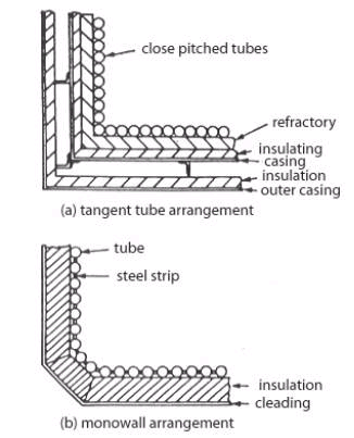
Fig 2.
Tangential and monowall arrangement
(Source: Seamanship International PC CD-ROM Engineering Knowledge)

In the tangent tube arrangement closely pitched tubes are backed by refractory, insulation and the boiler casing. In the monowall or membrane wall arrangement the tubes have a steel strip welded between them to form a completely gas-tight enclosure. Only a layer of insulation and cladding is required on the outside of this construction.

The monowall construction eliminates the problems of refractory and expanded joints. However, in the event of tube failure, a welded repair must be carried out. Alternatively the tube can be plugged at either end, but refractory materials must be placed over the failed tube to protect the insulation behind it. With tangent tube construction a failed tube can be plugged and the boiler operated normally without further attention.

Sometimes it is difficult to find the failed tube, in an exhaust gas boiler with closely fitted finned tubes for example, a method, which has found success, is ultrasonic detection.
Equipment required is a microphone pickup, connected to an oscilloscope.
• Pressurise the tube stack and headers with air.
• Enter the gas space with the microphone pick up.
• Go round the tube stack with the microphone.
• The maximum air hiss will give the maximum deflection on the oscilloscope.
• The leaking tube will be in that area.
Temporary Repairs To Membrane Or Monowalls At Sea (Ships’ Personnel)
The method of tube repair used in an emergency at sea would depend principally on whether a competent welder and machine are available. If not, the suitable plugs or expandable blind nipples for each of the failed tubes, should be available and also a supply of protective refractory to prevent subsequent burning through of the casing in way of the blanked-off tube.

(a) Welded repairs:

Welded repairs are usually of a patch nature and have the advantage that as the tube remains in use it is not necessary to protect it with refractory. A butt welded patch is preferable, but as this, and also any internally fitted patch, are liable, in the hands of an inexperienced welder, to result in weld splatter entering the tube bore, it is safer for a quick temporary repair to rely on an external fillet welded patch. For repairs of this nature the defective part of the failed tube is cut back to sound material and then a patch piece, preferably cut from a tube having bore equal to the outside diameter of the failed tube, is filet welded over the removed section of the failed tube – the overlap being kept small to prevent subsequent overheating when in service. Subject to a satisfactory hydraulic test on completion such a repair should allow the vessel to reach a port where permanent repairs can be effected (see below).

12
Fig 3.
Permanent welded repair
(Source: Seamanship International PC CD-ROM Engineering Knowledge)

(b) Mechanical repairs:

If a welded repair is impracticable the tube may be plugged at both ends providing the tube is subsequently protected by refractory to prevent local burning of tubes and possible the boiler casing.

Various mechanical plugging methods have been devised by the boiler designers, but lack of internal access and the high temperatures appertaining at shut down can make this an extremely unpleasant and/or lengthy operation. Two methods are described below:

123
Fig 4.
Permanent Mechanical repair
(Source: Seamanship International PC CD-ROM Engineering Knowledge)

Method 1. Windows are cut in the tube about 62mm from its extremities through which wires with taper plugs attached can be pulled the taper plugs having been inserted into the headers via the inspection doors. The plugs are pulled into position through pieces inserted across the windows, and are then pulled up solids by nuts.

After both ends of the tube have been plugged in this manner the whole length of the defective tube and the boiler casing behind it are shielded from the furnace heat during subsequent steaming by a thick shield of plastic refractory.

Method 2. Again windows are cut at each end of the tube through which blind nipples are inserted and subsequently expanded.

It will be appreciated that in this method boiler pressure tends to blow the plugs out whereas in Method 1 boiler pressure tightens the plugs in the hole. It is important to ensure therefore that with this method the expander rollers project down the bore of the nipple beyond the header or drum thickness so that an internal anti blow-out ‘collar’ is formed on the nipple during expanding; as a double precaution special ‘stepped’ roller can be used to form this collar.

As in Method 1, the whole length of the failed tube has subsequently to be shielded from the furnace heat.

Repairs To Membrane Or Monowalls In Port
The type of repair whether accepted as permanent or semi-permanent will depend largely on the availability of welders skilled in this type of work.
Inserting a new section
The obvious and most straightforward permanent repair consists of cutting out the defective length of tube along with part of its adjoining membranes and butt welding in a new section. This repair entails the services of skilled welders, the removal of casing and refractory in way of the repair, and accurate weld preparation.

1234
Fig 5.
Insert repair
(Source: Seamanship International PC CD-ROM Engineering Knowledge)

It is important to note that unless welders skilled in the type of repair are available, the surveyor should insist that the welders being employed do a preliminary procedure test to his satisfaction.

Fish mouth tube replacement method
23
Fig 6.
Fish mount tube replacement method
(Source: Seamanship International PC CD-ROM Engineering Knowledge)

This method, when carefully executed, is also acceptable as a permanent repair and has the advantage that as all welding is done from the furnace it is not necessary to disturb the boiler casing and refractory.

The defective part of the tube along with part of its adjoining membranes are burnt out, as in the previous method. The replacement piece of tube is prepared with its top and bottom ends cut off at 45° to give access when the replacement is in position for welding, from the furnace, the rear part of the two circumferential butt welds.

When these rear parts of the circumferential welds have been satisfactory completed, wedge-shaped pieces of tube are welded into the two windows, and the circumferential butt weld then complete working from the outside. The membranes are subsequently closed by welding as in the previous method.

The configuration of the wedge pieces can be varied to suit tube diameter and access required and, if necessary, backing rings may be used.

The loose ring method
34
Fig 7.
Loose ring method
(Source: Seamanship International PC CD-ROM Engineering Knowledge)

In ports where it is doubtful whether the experience of the welders justifies their employment on the previous two methods of repair, it is possible by this ‘loose ring’ method, to make an acceptable repair of a semi-permanent nature using down hand welding.

In this method access has to be made all around the tube and loose rings with cupped upper surfaces are slid into position in way of the butts to be welded, so that an inexperienced welder has a better chance of making a butt cum fillet joint. In all other aspects the repair is as in the previous two cases.

In view of the extra metal thickness in way of the rings and possible build up of weld metal this repair could subsequently be the subject of overheating in service, and on that account the repair should only be regarded as semi-permanent.

Testing

On completion of any of the foregoing repairs whether temporary or permanent, the boiler should be subjected to a working pressure hydraulic test. In the case of the repairs effected in port the welds should be crack detected and, if possible, X-ray detection equipment should be used.

REFERENCE

1. Leslie Jackson & Thomas D Morton Reed’s General engineering knowledge for marine engineers (2002) Thomas Reed, pgs 89 – 136
2. Leslie Jackson & Thomas D Morton, Reed’s Motor engineering knowledge for marine engineers (2002) Thomas Reed, pgs 178 – 198
3. Seamanship International PC CD-ROM (2004) Engineering knowledge
4. www.marineengineering.co.uk
5. www.marinediesels.info