Author Archives: Mohammud Hanif Dewan

COC ORAL EXAM PREPARATION (PART – 19): ENGINE ROOM WATCH KEEPING

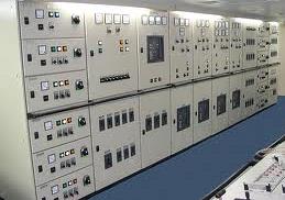
Watch Keeping in Engine Room:

pic05_up
Image Credit: www.jamstec.go.jp

A. Handing over a watch:

Engineers on ships perform their duties in rotational shifts, each having fixed and equal number of hours. This work shift, also known as a watch, needs to be carried out in an efficient manner to ensure the safety of life and property at sea. The normal watch keeping schedule and responsible watch keeping engineers in a fully manned engine room:
0800-1200——4/E,  2000-2400—-4/E
1200-1600——3/E,  2400-0400—-3/E
1600-2000——2/E,  0400-0800—-2/E

  1. A watch keeping engineer should take extra care while handing over the watch to the incoming watch keeping engineer to make sure that the ship runs safely and smoothly.
  2. It is  necessary that the right information is passed to the incoming engineer by the engineer on watch so that he can concentrate on his watch and perform more demanding and important jobs.
  3. Handing over of the watch should be carried out according to the instructions provided by the chief engineer’s standing orders and company’s instructional manual. It should be done very sincerely and honestly so that the watch keeping becomes smoother and continuation of any kind of work is not affected on the ship.
  4. The following things need to be informed to the reliving officer:
  5. Special orders related to any ship operation from bridge or the company
  6. Standing orders from the chief engineer
  7. Special mode of navigational operation of ship in case of emergency situation, damage, icy, or shallow water etc
  8. In case there is any kind of maintenance work being carried out in the engine room by other engineers and crew members then their work location, details of machinery under maintenance, and information of authorized person and crew members should be provided.


  1. Any potential hazard because of the ongoing maintenance work should also be informed.
  2. In case there is any equipment failure, details of the same should be informed
  3. All the checks already made when the ship leaves the port should be noted. In case any check is pending, it should be conveyed to the incoming watch keeping engineer
  4. All the checks that are made when the ship enters the port should be noted and informed in case any is missing.
  5. Condition and important information regarding mode of operation of main engine, boiler, and auxiliary engines should be informed
  6. Level of important tanks such as bilges, ballast tank, sewage tank, reserve tank, slop tank, fuel tank, or any other tank which requires attention
  7. Condition and state of fire extinguishing equipment and systems, in case any specific section or fire alarm has been isolated
  8. In case an equipment needs to be monitored manually, details of the same should be provided, along with the condition of monitoring and control equipment
  9. Any form of adverse ship condition needs to be informed
    • Information on the condition and modes of all the important auxiliary machinery such as purifiers, fresh water generator, oily water separator, pumps, sewage treatment plant, should be provided
    • Stand by machinery are at Standby mode and emergency equipments are at ready mode.
    • If any machinery runs in manual mode for special precaution need to be informed (for example F.O. Transfer pump or boiler feed pump etc)
    • In case any important machinery failed to receive attention during the watch, the reliving officer should be reported and asked to take care of the same
    • The condition and modes of automatic boiler controls and details of other equipment related to the operation of the steam boiler should be provided
    • The engineer officer should ensure that all the important parameters regarding main and auxiliary machines are suitably recorded in the engine room log book.
    • Main and Auxiliary machineries, boiler, A/C, refrigeration, steering, electrical motors, alternators etc. in good order or any changes from normal, abnormality to be informed.
    • Status of communication with bridge to be informed.
    • Environmental protection in good order e.g. smoke etc is in acceptable level and ppm & alarm of OWS if it is running
    • M/E rpm/ ship speed status
    • Log Book updated in time, all parameters logged down, meter readings recorded as appropriate
    • For and UMS ship alarm record book and equipment check lists to be verified
    • If you are satisfied that the incoming watch keeping engineer is in fit/good condition; not drunk etc. and mentally and physically prepare to take over the watch then hand over the watch to him by signing company form.
    • if in doubt,  inform and consult with the chief engineer officer.

B. Taking over a watch

  1. For taking over a watch get ready with proper PPE at least 20 minutes before the watch. Then if not restricted area go outside the accommodation to see the M/E and Aux Engines exhaust gas colour from the funnel.
  2. Then Come down to the engine room in time, take a good round to feel for any abnormality in sound, smell etc.; check for any leak, contamination, level, pressures and temperatures of all running machineries:
  •  ME  or propulsion systems functioning and all units’ exhaust temp, piston cooling lub oil outlet temp, JCW outlet temp, Lub inlet pressure & temp, Air Cooler temp, fuel temp & pressure to be checked.
  •   Aux Engine system functioning and all units’ exhaust temp, piston cooling lub oil outlet temp, JCW outlet temp, Lub inlet pressure & temp, Air Cooler temp, fuel temp & pressure to be checked.
  •   Steering system functioning and tank oil level to be checked.
  •   Boiler pressure and water level to be checked. Also check the hotwell water level.
  • Accommodation A/C and provision refrigeration plants to be checked and  provision rooms temp to be checked too.
  •   EGE/EGB inlet & outlet exh temp to be checked.
  •   Bilge level in all bilge wells and bilge holding tank to be checked.
  • Sludge tanks and BSO tanks level to be checked.
  •  Purifier fuel temperature, pressure and gear oil level to be checked.
  • Air Compressor runs in auto and air bottles pressure maintaining. Air Compressor oil level to be checked.
  • Drain fuel oil settling and service tanks and check the level & temperature.
  • Air Bottles to be drained and pressures to be maintained.
  • If the incinerator runs, waste oil service tank level and temperature and incinerator furnace temperature to be monitored.
  • Sewage treatment plants to be check for proper functioning
  • Environmental protection in good order e.g. smoke etc is in acceptable level.
  • Safety related items e.g. fire alarms and fire extinguishing system to be checked for proper functioning or any abnormality.

3.  Then after coming back to the control room, check the control panel for any abnormal alarms or parameters.

4. Check the main electrical switch board for running D/G load, volt and amp and stand-by mode of other idle D/G. Also check the megger readings and lamp indications for earth faults in 440Volt or 220 Volt feeder panel.

5. Then check M/E rpm, T/C rpm and M/E load indicator and ask about C/E and bridge instruction for M/E rpm.

6. Ask the following information from relieving engineer before taking over the watch:

    •  Any special orders related to any ship operation from bridge
    • control system or manual operation of any machinery in engine room & deck if any
    • Standing orders from the chief engineer
    • Special order from the company or master
    • Level of important tanks such as bilges, ballast tank, sewage tank, or any other tank which requires attention
    • Condition and state of fire extinguishing equipment and systems, in case any specific section or fire alarm has been isolated
    • Special mode of navigational operation of ship in case of emergency situation, damage, icy, or shallow water etc
    • Any ongoing maintenance jobs in E/R and any potential hazard associated with ongoing maintenance works.
    • In case there is any equipment failure,
    • In case any check is pending after full away or notice for arrival in port
    •  Any condition and important information regarding mode of operation of main engine, boiler, and auxiliary engines
    • Any equipment is running on manual mode
    • Any important machinery failed to receive attention during the watch,

7.  Before taking over , the log book should be checked and ensured that all the important parameters regarding main and auxiliary machines has been recorded and updated in the engine room log book by outgoing watch keeping engineer and signed.

Accepting Watch

    • If all above check points are covered satisfactorily, watch is taken over smoothly. If in doubt – may inform and consult with chief engineer
    • Compilation of machinery space log book & understanding significance of readings taken
    • In general while taking over/handing over a watch, considering a smooth running operation, all parameters – pressure, temperature, level, flow meter reading etc. are  normal and logged down in the log book accordingly. Should there be any abnormality following significant difference will appear:
  1. Change in temperature and pressure will indicate deviation/abnormality, considering same ambient condition
  2. Different level condition indicates loss, leakage, overflow etc.
  3. A distillate plant flow meter small (red new) reading may indicate performance fall off.
  4. FO/DO flow meter increased reading may indicate loss of above, leakage etc.
  5. In brief any change in log book parameters will help to make out difference between condition monitoring and easily detects some fault with relevant machineries and indicate their performance.

C. Duties of a watch keeping engineer during an engine room watch:

During the engine room watch, the following machineries to be monitor regularly:

    •   ME  or propulsion systems functioning and all units’ exhaust temp, piston cooling lub oil outlet temp, JCW outlet temp, Lub inlet pressure & temp, Air Cooler temp, fuel temp & pressure to be maintained.
    •   Aux Engine system functioning and all units’ exhaust temp, piston cooling lub oil outlet temp, JCW outlet temp, Lub inlet pressure & temp, Air Cooler temp, fuel temp & pressure to be maintained.
    •   Steering system functioning and tank oil level to be maintained. System to be greased or lubricate.
    •   Boiler pressure and water level maintaining.
    • Accommodation A/C and provision refrigeration plants to be checked and  provision rooms temp to be maintained.
    •   EGE/EGB soot to be blown.
    •   Bilge level to be checked and if necessary, bilge to be transferred in Bilge holding tank.
    • Sludge tanks level to be checked and if required, sludge to be transferred in BSO tank.
    •  Purifier fuel temperature, pressure and de-sludging in time.
    • Air Compressor runs in auto and air bottles pressure maintaining
    • Drain fuel oil settling and service tanks and maintain proper level and temperature.
    • Air Bottles to be drained and pressures to be maintained.
    • If the incinerator runs, waste oil service tank level and temperature and incinerator furnace temperature to be monitored.
    • Sewage treatment plants to be check for proper functioning
    • Environmental protection in good order e.g. smoke etc is in acceptable level.
    • M/E rpm to be maintained according to C/E instructions.
    • Safety related items e.g. fire alarms and fire extinguishing system to be checked for proper functioning.
    • Additionally check for any bad smell, abnormal sound, and look for any abnormality, leakage, level etc.
    • In fact a good watch keeping helps keep aware of any changes and decision can be made out accordingly.
    • Bridge/chief engineers any instruction should be completed with
    • Any pending repairs, bilge, ballast operations to be supervised carefully.
    • During any congested water navigation, bad weather, appropriate decision should be taken. For any kind of problems with main/auxiliary machines, bridge/chief engineer officer to be informed as appropriate, meanwhile preventive/corrective action to be taken.
    • Safety precautions to be observed during a watch and immediate actions in the event of a fire or accident by informing bridge and chief engineer.

What precautions to be observed during a watch?

  1. Regular rounds to observe for bad smell, abnormal sound/noise,leakage,level etc.
  2. Main, auxiliary machinery, steering gear etc. pressure temperature, level maintained normal, main engine RPM, vessel speed normal
  3. Boiler, pressure, level, A/C, refrigeration, pumps etc in order
  4. Exhaust/smoke checked clear, bilge level, normal, fire duties, active
  5. No undue bilge level, ballast, transfer operation taking place.
  6. Take corrective actions to change in parameters and inform chief engineer/bridge when appropriate.

 What immediate action you are going to take in the event of a fire or accident?

Ans:    The Abbreviation of Fire:

F – Find         or                 Find

I –  Inform                          Isolate

R – Restrict                         Report

E – Extinguish                     Extinguish

Hence on viewing a fire isolate the source of combustion and inform the bridge and Chief Engineer, raise fire alarm, so that others will remain aware of the situation, will muster & come to help.

Meanwhile try to extinguish the fire with appropriate means.

Should there be any accident inside E/R, inform bridge, Chief Engineer and raise emergency alarm so that  other crew members will muster and come to help/rescue as appropriate. Meanwhile take corrective actions as deemed necessary.

COC ORAL EXAM PREPARATION (PART – 18): ELECTRICAL MISCELLANEOUS

Servicing a motor effected/washed by seawater:

  1. Cut out power supply by circuit breaker & taking out fuse. Mark & disconnect supply wire. Took Megger reading & recorded.
  2. Take out the motor, open up & dismantle. (Make sure marking on both cover & body)
  3. Clean and wash with warm fresh water.( About 180′ F)
  4. Cover by canvas, dry with positive ventilation & 500 watt lamp
  5. Clean with Electro cleaner.
  6. Baking by 500 Watt lamp for few hours.
  7. Take Megger reading. (test stable or constant reading) Apply insulation varnish to the winding while warm.
  8. Baking & taking the Megger.
  9. Reassemble & put back into service.
  10. When test run check sound, ampere & temperature.


Safety device on alternator:

  1. Heater
  2. Cooling fan.
  3. Reverse power trip.
  4. Preferential trip.
  5. Over current trip.
  6. Under voltage trip.

Windlass safety device:

  1. Slipping clutch.( Fitted between hydraulic motor and gear)
  2. Over load trip.

Winch safety device.

  1. Over load trip.
  2. Centrifugal brake.
  3. Magnetic brake.
  4. Limit switch for runner, topping & slowing.
  5. Hydraulic oil high temperature alarm & cut out.
  6. Hydraulic oil over head tank low level alarm.

Megger:

A Megger is an ohmmeter to measure insulation resistance in million of ohms. (Pole to pole, pole to earth). Good insulation has high resistance; poor insulation, relatively low resistance. The actual resistance values can be higher or lower, depending upon such factors as the temperature or moisture content of the insulation (resistance decreases in temperature or moisture).

Purpose of Megger Test:

  1. To verify insulation resistance.
  2. To detect any insulation fault.

Correct Procedure to Check Megger:

Switch off main switchboard by means of circuit breaker & taking out fuse, put label of MEN AT WORK, disconnect the connection from stator, teat with Megger Meter. Measure during hot condition resistance for accurate reading.

The Megger insulation tester is essentially a high-range resistance meter (ohmmeter) with a built-in direct-current generator. This meter is of special construction with both current and voltage coils, enabling true ohms to be read directly, independent of the actual voltage applied.

This method is non-destructive; that is, it does not cause deterioration of the insulation.

(Image Credit: electrical-engineering-portal.com)

Fig: Megger test instrument hook-up to measure insulation resistance.

The generator can be hand-cranked or line-operated to develop a high DC voltage which causes a small current through and over surfaces of the insulation being tested (Fig). This current (usually at an applied voltage of 500 volts or more) is measured by the ohmmeter, which has an indicating scale.

Safety device on switch board:

  1. Circuit breakers
  2. Over current relay (OCR) for protection from high current
  3. Reverse power trip
  4. Preferential trip
  5. Under voltage trip
  6. Fuse
  7. Earth lamp
  8. Synchroscope, synchronising lamp.
  9. Meter (ampere, frequency, volt, watt)
  10. Dead front panel safety device provided on the Main switch board individual panels wherein you cannot open the panel until the power of that panel is switched off.

Shore supply connections

  • Where arrangements are made for the supply of electricity from a source on shore or other location a suitable connection box has to be installed in a position in the ship suitable for the convenient reception of flexible cables, it should contain a circuit breaker or isolating switch, fuses, and terminals of adequate size to receive the cable ends.
  • For three phase shore supplies with earthed neutral terminals are to be provided for connecting hull to shore earth
  • An indicator for shore side connection energised is to be provided.
  • A means for checking polarity or phase rotation is to be provided
  • At the connection box a notice indicating ships requirements with respect to supply as well as connection procedure.
  • Alternative arrangements may be submitted for consideration.

How will you know the shore power supply is correct or not?

  • Phase sequence indicator.(inside shore connection box, turn clock wise direction)
  •  Operate E/R vent fan & check airflow direction.

When excitation loss:

  •  Tapping with hammer to field coil core of excitation motor.
  • Energise with battery.

Preferential trip:

 If a generator overload condition develops, its preference overload trip will operate to energise the timing relay. The timing relay then operates to disconnect non-essential services in a definite order and at definite time intervals.

  •  None essential (without effecting the ship operation.)           5 sec:
  • Essential     (running the ship properly)                                     5 sec:
  • Top polarity     (propulsion, navigation)                                   15 sec:

Static electricity:

  • Electricity produced on dissimilar materials through physical contact & separation
  • Out going material negative, remaining material positive.

Spontaneous combustion:

The ignition of material brought about by a heat producing exothermic chemical actin within the material itself, without exposure to an external source of ignition. (Wet oily rags, wet saw dust)

Armature reaction.

 –  When a D.C generator or a motor is operating with load, sparking between the carbon brushes and the commutator results due to Armature Reaction. Armature reaction takes place when the armature current flows in the armature.

–  When current flows in armature, the armature core is magnetising by this current. Magnetising effect of the armature current can be divided into two effects: –

  • Cross magnetising or distorting effect.
  • Demagnetising or weakening effect.

To compensate the Armature reaction, modern Electrical Machines are provided with

  • Interpoles
  • Carbon brush rocker.
  • Neutralising Winding.

A.C motor starters: 

A motor starter is an apparatus used for controlling the starting of an electric motor.

  1. Direct on line starter.(without current limiting element)
  2. Resistor or rheostatic starters.(with current limiting device)
  3. Star delta starter.
  4. Auto Transformer starter.(reduced voltage starting 55%, 60%, 70%, full voltage running
  5. Rotor resistance starter.(starting slip ring induction motor)

Dash pot 

Mechanical device to produce a time delay action. Operation of switch gears, arc lamps, motor starters, Electro magnetic bake, etc. Time delay is adjusted by oil viscosity used.

Earth detecting lamps

  • The earth fault detector consists of three incandescent lamps which are connected in star. These three lamps are supplied from the secondaries of three single phase step down transformers. The primaries of three transformers are connected in star. The star point of the primaries is connected the frame of the ship. The primaries of these transformers are fed from the red phase, yellow phase and blue phase of the ship supply.
  • Giving visual signals and buzzer will sound when there is an Earth fault in the system on board.
  • Three incandescent lamps which are connected in star. These three lamps are supplied from the secondaries of three single-phase step down transformers.
  • The primaries of these three transformers are connected in star. The star point of the primaries is connected the Frame of the ship. The primaries of these transformers are fed from the Red phase, Yellow Phase and Blue Phase of the ship supply main.
  • No Earth Fault in the system, Lamps will glow with equal brightness.
  • When earth fault occurs one of the phases, the lamp on that phase will become dark and other two lamps will burn with extra brightness.
  • Earth fault can be traced by switching off the branch circuit breaker one by one. When the branch circuit with the fault is switched off, the earth lamp will return to its normal glow.

Emergency power supply:

  1. Emergency lights.
  2. Navigation lights.
  3. International communication equipment.
  4. Day light signalling lamp.
  5. Ship’s whistle.
  6. Fire detecting and alarming installation.
  7. Manual fire alarm.
  8. Other internal emergency signal.
  9. Emergency fire pump.
  10. Steering gear.
  11. Navigation aid and other equipment.

Single phasing:

  • Single phasing is the term used to denote the condition arising in a three-phase circuit when one phase becomes open circuited.
  • The open circuit in a phase, often from a blown fuse, faulty contact or broken wire, will prevent a motor from starting but running motor may continue to operate with a fault.
  1. Excessive current in the remaining supply cable.
  2. Unequal distribution of current in motor winding.
  • Can be detected by overload device in the supply line or through the overheating.
  • Overheating in a stalled or running motor will cause burn out of the overloaded coil.
  • In a lightly loaded motor to remain undetected by electromagnetic trips on the supply line which monitor only current. Improve protection is given by thermisters placed in the winding to measure thermal effects.

Insulated neutral system

Advantages

  • This system avoids the risk of loss of essential services e.g. steering gear
  • If the neutral was earthed and a short circuit on one phase causes the fuse in that phase to blow the system would now be singled phasing and may burn out motors
  • In an insulated neutral, one earth fault does not interrupt the supply but an earth leakage detection system will give warning.
  • Low earth fault currents in insulated systems gives a much less fire risk.

Disadvantages

  • On the insulated system the voltage to earth is 1.73 Vph e.g. 440v vs 250v
  • Tracing an earth fault is more difficult because although selective tripping may trace the earthed circuit, the actual position on the circuits may still be difficult to locate. Resonant or intermittent faults in say a contactor solenoid or a transformer with an insulated neutral can cause voltages to be magnified to say 4 times the normal voltage to earth (250v x 4 = 1000v)

Note: electrical shock is not reduced by using a non-earthed neutral as large voltages are involved. Both systems are equally dangerous

Earthed neutral system

When an earthed neutral system of generation is used earthing is to be through a resistor. The resistor is to be such that it limits the earth fault current to a value not greater than the full load current of the largest generator on the switchboard section and not less than three times the minimum current required to operate any device against

Back E.M.F

  •  When a current flows through the conductors of an armature of a motor, a force will be exerted on the conductors. This force produces a torque, which will cause the armature of the motor to rotate.
  • When the armature conductors are moving across the magnetic field, these conductors will cut the magnetic lines of force and therefore generate an E.M.F. The direction of this generated E.M.F is opposite to the applied voltage of the motor. Since the generated E.M.F in the motor is opposite to the applied voltage to the motor, this E.M.F is called Back E.M.F.

Applied Voltage = Voltage drop to armature resistance + Back E.M.F

V          =                 Ir                                +           Eb

Automatic voltage regulator (AVR):    

Sudden load current surges (sudden great increase) (e.g. due to motor starting) on a generator cause a corresponding change in its output voltage. This is due to an internal voltage drop in the generator ac windings and the effect is usually called ‘voltage dip’. Similarly, load shedding (to get rid of it) will produce an over voltage at the bus-bars. An unregulated or non-compounded generator excitation system would not be realistic on board ship due to the varying voltage caused by the fluctuating load demand. Automatic voltage regulation (AVR) equipment is necessary to rapidly correct such voltage change.

  1. Carbon pile regulator.
  2. Vibration contact regulator.

The alternator output is transformed, rectified and output effect through magnetic coil against spring which are voltage reference and apply to dc exciter shunt field and rotor of alternator.

  1. Static automatic voltage regulator.

The direct current derived from the alternator output through transformer & rectifier, is applied to a bridge which has fixed resistances on two arms and variable resistances (zener diode voltage references) on the other two. When change in applied voltage, by Whetstone bridge produce an error signal. The error signal can be amplified and used to control alternator excitation in different ways. (Thyristor, Transistors in series)

Diode

  •   An electronic device that allows electrons to flow in one direction but in highly resistant to current flow in the opposite direction. (Similarly check in the piping system.)
  • The purpose of the diode is to function as a rectifier of higher frequency and low frequency oscillation. It is used as detector in a receiver circuit.
  1. Thermionic diode consists of a heater, a cathode and an anode, in an indirectly heated valve.
  2. Semi conductor diode is constructed with Mono crystalline germanium or silicon wafers with two layers differently doped; ‘pn’ junction acting as rectifier junction.

Transistor

  • Three layer device, either NPN or PNP
  • It has emitter, collector & base
  • Used small signal power from a side circuit controlling the larger power in other circuit. (Power gain or amplification)

Thyristor

  • Power control element. Multi -layer device of alternate P and N junction.
  • E.g.         Silicon controlled rectifiers (SCRs) ~ Four layer device.

Triacs ~ Greater number.

  • Thyristors are solid state switches, which are turned on by application of a low-level signal voltage through a trigger connection known as a gate electrode
  • No moving parts to wear, or contacts which can be damaged by arcing.
  • Ideal for remote operation. Small size ~ convenient component of control circuit. Can control current greater than 1000 amps and voltage in excess of 1000 volts. Replace large conventional switches.
  • Operate faster rate (25,000 times per second).

Exciter:

  • It is a small D.C generator. It supplies the exciting current to the rotor of the A.C generator.
  • Exciting current is current required to create any magnetic field.

Equaliser

An equaliser is a connection between the generators of different capacities running in parallel so that the running load is divided proportionately between the two.

D.C loads on A.C ship service system:

  1. General alarm system.
  2. Emergency lighting.
  3. Emergency radio power.
  4. Rectifying for battery charging.

Maintenance of motors:

  1. Keep air passage clean.
  2. Remove deposits of dust, oil and grease.
  3. Take insulation resistance reading.
  4. Prevent sparking at brushes and commutator.
  5. Mechanical check at bearings, holding bolts couplings.
  6. Regular check on motor starters and controllers, maintenance of contacts, resistance and connection.

Galvanometer:

It is an instrument for measuring the small electric current with its magnitude and direction.

Resistor:

It is a device, which conducts electricity but converts part of the electrical energy into heat.

Resistivity:

It is a resistance of a material and expressed in ohms/unit length.

Rheostat

It is a resistor, which is provided with means for readily adjusting its resistance.

Fire fighting at switchboard

  1. First of all the circuit breaker to be break out. Then extinguished with the fire with CO2 portable extinguisher.
  2. After fire is stop, the switch board is cool down
  3. All wire system must be traced and continuity test.
  4. After tracing and renewing all fittings, the switchboard can be put back into service.

Fire Prevention:

  1. Use correct fuse.
  2. All contacts of circuit breakers and switches are well contact.
  3. All wire connections are well lapped.

Causes of Fire:

  1. Loose contact.
  2. Incorrect fuse.
  3. Insulation break down

Residual magnetism:

When starting up a generator, the necessary magnetism is provided by the iron cores of the field poles. This magnetism is known as residual magnetism.

Battery installation and safety measures:

  1. Require good ventilation for H2 involving. Require suitable paint to outlet vent ducts. Ventilation inlet should be below battery level.
  2. Naked light and smoking are prohibited in battery room.

Lap wound.          Multi parallel circuit in armature.

Wave wound        Two parallel circuit in armature.

Failure to excite:

  1. Loss of residual magnetism.
  2. Too high resistance in the field circuit.

Universal motor:

  1. Series wound.
  2. Single phase.
  3. Either A.C or D.C can be used.
  4. Fractional(very small) power. (Less than 1 HP.)

Used on sewing machine, portable drill, etc.

(When the motor is attached to D.C line, the current is in the same direction all the time. In an A.C  line the current is reversing itself every cycle.)

What are the likely consequences of attempting to close the incomer’s Air Circuit breaker (ACB) when the generators are not in synchronism?

At the instant of closing the breaker, the voltage phase difference causes a large circulating current between the machines which produces a large magnetic force to ‘pull’ the generators into synchronism. This means rapid acceleration of one rotor and deceleration of the other. The large forces may physically damage the generators and their prime movers and the large circulating current may trip each generator breaker. Result? Blackout, danger and embarrassment!

Synchronising:

  1. Synchroscope
  2. Synchronising lamp:
  • ‘Dark’ lamp method. (2 lamps)
  • ‘Bright’ lamp method. (2 lamps)
  • ‘Sequence’ method.(3 lamps)

How could you monitor the correct instant for synchronising without the aid of a Synchroscope or synchronising lamps?

Connect pair of 500 V voltmeter probes across one phase of the incoming machine circuit breaker. Adjust the generator speed until the voltmeter slowly fluctuates from zero to maximum. Close the breaker when the voltmeter passes through zero.

SHIPBOARD PREPARATION FOR ICE IN WINTER SEASON

New Bitmap Image

Image Credit & Author: Captain Kamal Ahmed.

Preparation

Prior making a voyage into subfreezing zone, Master must ensure that the vessel is suitable for navigating in that zone, crew are duly trained, well protected with PPE and necessary gears and familiar with the operations of the vessel in ice conditions. Master also need to prepare his or her vessel to encounter severe winter condition to prevent damages to the vessel and or its machinery prior entry in areas in freezing condition.

34 35

Ballasting & De-ballasting

  • While pumping out Ballast Water from the Cargo Hold, there is a tendency of ice forming on the frames & girders. Consider heating holds by Electrically Operated Heaters.
  • For sounding Ballast Tanks, sometimes it will be useful to blow hot air through the air pipe. It may be necessary to frequently pour Glycol or clear the sounding pipes with sounding rod.
  • Ballast tanks should be maximum 90% full to allow expansion due to freezing. Care must be taken by pumping ballast in and out to ensure that the vent pipes are not blocked with ice.
  • De-ballast one tank at a time. Continue stripping without any break.

Equipment & Apparatus

  • At temperature below -30C, move the rudder Port & Starboard side enough to keep the Rudder Stock free.
  • Propeller and Bow Thruster should be well below water.
  • Anchor should be free and ready to be moved from the hawse pipe position. The pumps for Windlass and Mooring Winches should be running at all the times.
  • Lifeboat Engine & Emergency Generator should be filled up with Anti-Freeze. Pay attention to fresh water tanks in life boats ( leave some void).
  • Emergency fire pump suction strainer should be free of ice and the pump should be ready for use at all times.
  • Make sure sea that the chest vent is not choked/frozen and its valve is left open. Never use compressed air to clear sea chest in operation as it will create an airlock in the SW cooling system.

Pipe Lines & Valves

  • Fire Line should be drained out and blown with air. The anchor wash line should be drained out.

36 37

Draft Marks

  • During winter, sometimes it is not possible to read the Draft It may be helpful to take the Photographs of Draft Marks for obstruction by Ice and issue a Note of Protest Letter, witnessed by the Agent.

39

Forward Draft mark, Starboard Side covered with thick 25cm (approximately) ice

40 

 Navigation & Manouvering:

  • If the air temperature is below freezing, avoid taking head wind and sea spray which forms ice on the Fore Castle and on If necessary reduce speed. It is better to lose a few hours than a complete week in port “Off-Hire” with an expensive de-icing shore crew. There was an instance where the ship owner had to pay USD 50,000 for an Electrical Jack Hammer to break 100 cm of thick Ice from the Hatch Covers (6 men/24 hours for 2 days).
  • Follow the weather routing for Insurance
  • The main engine must be ready to go astern any
  • To go astern, the rudder must be mid-ship to prevent the propeller and rudder from
  • To prevent the hull from damage caused by impact, enter the ice at low speed and then increase to moderate speed to maintain headway and control of the
  • Do not drop the anchor where ice is dense in order to avoid the danger of the anchor chain being

Bridge & Bridge Equipment

  • Ensure whistle/horn heaters remain “On” at all the
  • Radar scanners to be kept turning all the
  • Turn on navigation lights at all times (at sea).

Deck, Windlass, Mooring Ropes & Pilot Boarding Arrangement:

  • Ensure that all mooring ropes and wires on the drums are securely covered. No mooring ropes should be out at sea.
  • Gangway, Pilot Hoist, Windlass, Compression Bars should be greased.
  • Pilot transferring equipment and boarding procedure should be maintained.
  • Manila Ropes should not be used for lashing on deck as it becomes stiff in cold temperature. Polypropylene or synthetic ropes are suitable for this type of weather.
  • Deck & Muster Station must be free of Ice & Snow.

42

  • All forward Deck fittings and Air Pipes to be covered by burlap & coated with grease mixed with

43

An accumulation about 350 M/T of ice on Deck.

Crew protection:

  • Heating in the accommodation shall be always in working condition.
  • The entire crew must be provided with proper winter clothing.

ISM Code

The ISM Code is intended to address risks associated with ship operations and establish well documented vessel specific procedures and practices. The Crew members designated to the vessel are required to possess skills and knowledge essential for the safe execution of tasks they are expected to perform in normal day to day operations and during emergency situations.

Ice-Accretion

Ice-accretion on super-structure / containers / deck-cargo /masts can seriously imperil the vessel’s stability. Sufficient GM (F) to counteract same must be maintained.

Canadian Regulations

  • Every Ship of 100 tons gross or over, navigating in ice covered waters of Eastern Canada must have and use the publication “Ice Navigation in Canadian Waters (TP5064).
  • Canadian regulations require that all vessels navigating in ice to be equipped with a system to prevent icing and chocking of sea chests and to maintain an essential cooling water supply. (Ref: Canadian Marine Machinery Regulations-SOR/90-264). Icing/blockage could occur between December to March.
  • Transport Canada strongly recommends to have onboard and to have all personnel knowledgeable of the following documents:
    a) Winter Navigation on the River and Gulf of St. Lawrence Practical Notebook for Marine Engineers and Deck Officers (TP14335/Edition 2011)
    b) Joint Industry-Government Guidelines for the Control of Oil Tankers and Bulk Chemical Carriers in Ice Control Zones of Eastern Canada (TP15163/Edition 2011).

Useful links:

http://publications.gc.ca/site/archivee-archived.html?url=http://publications.gc.ca/collections/collection_2010/tc/T29-85-2009-eng.pdf http://www.ccg-gcc.gc.ca/Icebreaking/Ice-Navigation-Canadian-Waters/Navigation-in-ice-covered-waters

By Capt. Kamal Ahmed.

COC ORAL EXAM PREPARATION (PART – 17): BOILER SAFETY VALVE

Boiler Safety Valves protect the boiler from over pressurisation. As per the requirements, at least two safety valves should be fitted to the boiler and both are mounted on a common manifold with a single connection to the boiler. Boiler with super heater, normally three safety valves are fitted; two to the boiler drum and one to the superheater. The superheater must be set to lift first to ensure a flow of steam through the superheater.

Improved High Lift Boiler Safety Valve:

1245

Fig: Improved Highlift Boiler Safety Valve

The sketch shown is improve high lift safety valve . The are usually mounted 2 Nos. on a single chest. Valve , seat , spindle , compression screw and bush are made of non-corroded metal and valve chest is made of cast steel.
This valve improve than other type as because:

  • Using wingless valve to improve steam flow
  • Floating cylinder arrangement can prevent piston seizure.


The special shaped valve and seat deflect steam toward the lips on the valve and increase valve lift.This action also achieves the valve to lift and shut smartly at the blow off pressure. It is set to open at 3 % above working pressure. The lift of valve is one twelfth of the valve diameter.

A ported guide plate fitting adequately guide the spindle itself and allow the waste steam to the under side of the piston with pressure and gives increased valve lift.  Waste steam pressure also keeps the floating cylinder in place while the piston moves. So floating cylinder seizure risk is reduced.

A drainpipe is fitted to the lowest part of the valve chest on the waste steam discharge side and lead to clearly drain,  no valve or cock fitted through its length. This drain is important to be checked regularly. If it is choked, there is a possibility of overload  to valve , due to hydraulic head and damage results by water hammer.

boiler-high-lift-safety-valve145

Fig: Boiler High Lift Safety Valve

Close examination and attention during overhauling

  • Check valve and seat for wear, cavity corrosion , pitting and any fault. They must be ground in properly not to excess  maker’s limited dimensions and clearances.
  • Valve chest must be cleaned condition and drain line clear
  • Hammer test to spindle for any crack and check its straightness
  • Hammer test to compression spring for any fracture and check for corrosion. Free length is limited to 0.5 % of original free length.
  • Check the guide plates and bushes for uneven wear and have sufficient clearance to allow free movement of
  • Check compression nut and cover bush’s threads and any sign of wear and tear.
  • Check the easing gear , cable , pulley and connecting links.
  • Connecting pin should be a free fit in the lid and no bending. Pinhole to be regular shape.

 Pressure setting of safety valve

  • Take standard pressure gauge
  • Shut boiler main stop valve and feed check valves
  • Check waster steam pipe and drain line clear
  • Ensure the correct assemble of valves with no hood and easing gear
  • Keep the boiler under full fire condition with adequate water level visible in the sight glass.
  • Bring up the boiler pressure to the required blow off pressure, 3 % above the approved working pressure.
  • Screw down the compression nuts of any lifting valves until all quiet.
  • Then adjust each valve in turn by slacking of its compression nut until its valve lift.
  • Subsequently screw down the compression nut while lightly tapping its Spindle , valve will return to its seat and remain properly seated.
  • Measure gap between compression nut and spring casing cover. Make compression ring with sane thickness to this gap measurement and insert under the compression nut.
  • Retest the valves lift and close together.
  • Then , fit the cap , cotter pin and easing gear
  • Cap and cotter to be pad locked to prevent accidental alternation of setting.
  • Test the safety valve with easing gear to satisfaction for emergency .

Accumulating pressure test

The accumulating pressure test is done to limit the excessive pressure rising in boiler while the safety valve is open, cause further compression of spring due to increased loading. .

The test is carried out, on the new boilers or new safety valves , under full firing conditions, with feed water and steam main stop valve is closed. The test is continued for as long as the water in the boiler permits but it need 15 minutes for a tank type boiler and 7 minutes for a water tube boiler. With the safety valves operating, accumulation must not exceed 10% of the working pressure.

HIGH PRESSURE WATER MIST (HYPER MIST) SYSTEM

  • Mandatory in passenger ships with GT > 500 and cargo ships with GT >2000, for fire extinguishing in machinery spaces of category A with volume > 500 m3 (IMO MSC/Circ.913).
  • System introduced as an alternative to the Halon systems (prohibited in 1994) for fire fighting in machinery spaces of category A and cargo pump rooms. This fire extinguishing process is based in 3 mechanisms:
    –  Cooling of the flames
    –  Reduction of the oxygen content by the displacement of the air by the expansion
    of the water vapor
    –  Diminution of the radiating heat
  • The pressurized water in contact with the fire vaporizes and it is converted into steam. This process absorbs much energy lowering the temperature of the fire and the pressurized water expands about 1700 times taking the air away from the fire. These systems require a water consumption 6 to 10 times lower than a traditional sprinkler system
  • It shall be activated automatically by 2 different types of detectors:
    flame and smoke.


  • The requirements for test and approval of these systems are specified in the MSC/Circ.1165:
    – It shall be capable of being activated manually
    – It shall be always ready to function and be capable of supplying water during 30 minutes, to avoid the re-ignition of the fire
    – The systems that operate with a reduced output after and initial discharge, shall be ready again in less than 5 minutes
    – It shall have redundant pumping means and shall have a permanent sea chest
    – The means of control shall be outside the protected spaces
    – It shall be supplied with electric power from the main and emergency generators
    – The capacity of the system shall be based in the largest of the protected areas

The most common areas covered by water mist system in ships:

  • Incinerator room
  • Auxiliary boiler room
  • Auxiliary generators
  • Main engine cylinder head platform
  • Purifier room
  • Inert gas generator room
  • Steering gear room

Principles of High Pressure Water Mist System (Hyper Mist)

The Hyper Mist Fire Extinguishing System jets out uniform microfog out of nozzles of special specifications under a pressure as high as about 4 to 10 MPa (about 40 to 100 kgf/cm2). The water particle diameter is about 50 to 200 μm. Making use of water in the form of fine particles improves the fire extinguishing effect and efficiency. Moreover, it makes it possible to apply the system to those objects (oil fire, electric fire, etc.) which were considered conventionarilly difficult to be extinguished with water. With these water particles of 50 to 200 μm sizes, excellent fire extinguishing and suppressing performance has been demonstrated through many experiments.

Further, the hyper mist system has the following effects:

  • Cooling effect (quick cooling by evaporation latent heat)
  • Oxygen replacement effect (replacement of air with water vapor generated in a large quantity, and absorption of radiation heat)
  • Shut-off effect (the floating fog forming walls of water)
  • Smoke eliminating effect (the floating smoke particles being adsorbed and settled by the fog)

Hyper Mist Operating Procedure:

Hyper mist system control switch should be always selected in Auto Mode. However, it can be run as Manual mode too by turning the selector switch from Auto to Manual mode. It shall be activated automatically by 2 different types of detectors:
flame and smoke.

4


Image Credit: www.yamatoprotec.co.jp

Starting of Hyper Mist System:

In Case of Automatic Start: Hyper Mist system will be automatically started and discharge hyper mist into the protected area where fire is detected by the fire alarm system and both smoke and flame detectors activated together, and an audible and visible alarm is raised in that protected area.

In Case of Manual Start: Hyper mist system can be started manually from the control panel and from the local points whenever needed, independent of the fire alarm system.

Stopping the hyper mist system:

After extinction of a fire, the hyper mist system can be stopped manually by cancelling the fire alarm signal from the fire alarm system by pressing the “Stop” button on the control panel or local control point.

The following conditions must be maintained always to ensure hyper mist system is stand by for operation:

  • Sufficient water level must be retained in the designated fresh water tank
  • Always the power supply should be available.
  • The fire alarm system must be in operation.
  • Drain and test valves must be closed and well marked.
  • The area around the Hyper mist water pump must be clear of any obstructions.
  • A clear operation procedure for manual and auto operation be displayed.

Alarm Test:

  • Designated freshwater tank low level alarm shall be tried out by manually lowering the float.
  • Electric source failure shall be tested by removing fuse from the control panel.

Line Test by Blowing Air:

  • The whole piping system to be blown through with compressed air at a pressure of 7 to 8 bar.
  • Check the free passage of air from the nozzles.

Source: www.yamatoprotec.co.jp, SOLAS

COC ORAL EXAM PREPARATION (PART – 16): CO2 FLOODING SYSTEM

 Requirements of CO2 Room:

In CO2 flooding system, carbon dioxide bottles are placed in a separate room. The requirements for location, accessibility, use and ventilation of CO2 storage spaces as per IMO are:

  • Spaces for storage of cylinders or tanks for extinguishing gas should not be used for other purposes.
  • These spaces should not be located in front of the forward collision bulkhead.
  • Access to these spaces should be possible from the open deck.
  • Spaces situated below the deck should be directly accessible by a stairway or ladder from the open deck.
  • The space should be located no more than one deck below the open deck.
  • Spaces where entrance from the open deck is not provided or which are located below deck are to be fitted with mechanical ventilation.
  • The exhaust duct (suction) should be lead to the bottom of the space.
  • Such spaces should be ventilated with at least 6 air changes per hour.


CO₂ room safety arrangement:

1. Exhaust fan, and suction duct is provided at the bottom of the room. Any accumulated CO₂ from leakage at the bottom can be exhausted to atmosphere.
2. Cable operated Safety Valve is fitted on Pilot Cylinder discharge line.
It prevents accidental discharge of CO₂ from Quick Release Cylinders due to action of
leakage gas from Pilot Cylinder.
3. Relief Valves are fitted on each discharge line from cylinders so that leakage gas can safely dispose to atmosphere.
4. Check Valve is fitted in connection pipe between each cylinder discharge valve and manifold, so that leakage of one cylinder cannot effect other cylinder.
5. Each bottle has a combined Bursting Disc, which will rupture spontaneously at a pressure of 177 bar at 63΄C.
6. Pressure Gauge and pressure Alarm in the manifold.

Maintenance of CO₂ flooding system:

1. Weekly inspection for alarm system.
2. Bottles should be weighed yearly; level checked by ultrasonic or radio active isotope detector. Level reference mark should be provided. If 10% loss of weight, recharge them.
3. All the pulley, wire, rope and toggle must be free from dirt, scales and well lubricated.
4. CO₂ branch pipe and discharge nozzle should be cleared with compress air at two year interval.
5. Bottles should not be exposed to temperature of 60΄C.

Weighing of CO₂ bottle:
1. Bottles should be weighed yearly by special weighing device designed for this purpose.
2. It has a reference mark to determine 10% loss of weight.

CO₂ Quantity Calculation:  (by Regulation):

  • For cargo space, CO₂ quantity shall be sufficient to give a minimum volume of free gas, equal to 30% of gross volume of largest cargo space so protected.
  • For machinery space, CO₂ quantity shall be sufficient to give a minimum volume of free gas, equal to 40% of gross volume of machinery space so protected excluding the casing.

So, if weight of CO₂ / bottle  = 45 kg / bottle and Free gas volume of CO₂ = 0.56 m³/ kg.     then, Required CO₂ bottles for cargo space   = (0.3 x Largest cargo space gross volume) / (0.56 X 45)

and

Required CO₂ bottles for machinery space  = ( 0.4  x  Machinery space gross volume) / (0.56 X 45)

Machinery Space (Engine Room) CO2 Flooding Procedure:

11

CO2 System operation in Machinery Spaces:
A Co2 system of machinery spaces consists of a bank of Co2 bottles that can be operated from a remote place located away from the machinery spaces. The system also consists of pilot Co2 cylinders which control the activation of the bank of Co2 bottles. The Pilot cylinders are contained in a control box and are normally kept disconnected. The system is connected to the pilot cylinders and the control box with the help of steel wires or flexible pipes. All these pipes are fitted with a quick action coupling.

  • When the system is to be activated, the coupling in plugged into the corresponding socket. The valves of the pilot cylinders will be opened with the help of the levers in the main CO2 control system.
  • The CO2 from the pilot cylinders will open the system’s main stop valve.
  • The main stop valve has a piston which gets depressed due to the Co2 gas pressure and allows the pilot gas to flow to the bank of CO2 cylinders.
  • This pilot gas operates the cylinders’ valves. All these valves have an actuator which gets operated by the pilot pressure.
  • The detection of fire is done by various sensors installed in the machinery spaces.Though the opening of control box operates an alarm, the main decision for CO2 flooding is taken by the Chief engineer, after due consultation with the master of the ship.
  • Before releasing Co2 into the fire affected space, it should be made sure that everybody is out of the place and total head should be counted.
  • The place is fully enclosed i.e all skylights & ventilators are closed air-tight and pumpsumps supplying fuel oil should also be stopped in order to prevent re-ignition.
  • Separate levers for each and every space are present inside the main controlling cabinet. The operating of a particular lever activates the pilot bottles, which helps in releasing the complete bank of bottles designated for that place.
  • With the opening of the master valve, Co2 is flooded inside the fire affected space, which then smothers the fire with the help of blanket effect.
  • Boundary cooling should be carried out.

Machinery space minimum requirement:

1. Two nos. of fire hydrants with hoses, minimum.
2. 10 ft³ of sand and sawdust with scoops.
3. One fixed installation of CO₂ or foam or Halon.
4. Portable extinguishers of at least 2 nos. of 2 ½ gallon (11.37 litres) foam or CO₂, depending on BHP.
5. Semi-portable extinguishers of 45 kgs of CO₂.
6. Drip pans and trays for every F.O. and L.O. tanks.
7. Monitoring, detection and alarm system.
8. Emergency fire pump.
9. 2 nos: of main fire pumps.
10. International shore connection.
11. Inert gas system.

Machinery space fire fighting: by CO₂ flooding system:

1. CO₂ flooding to machinery space must be done by master’s order.
2. CO₂ must be released by competent engineer, CE.
3. When cabinet door is opened alarm will sound and all ER fans will be stopped.
4. Before releasing, all ER crew to be counted.
5. All openings must be shut [ventilator flaps, fire damper].
6. All fuel pumps and quick closing valves of fuel tanks and fuel transfer line must be shut from remote control position.
7. After opening the cabinet door, master valve must be opened first.
8. Pull the operating handle of pilot cylinders.
9. CO₂ , released from pilot cylinder, operate the gang release bar so that all CO₂ from quick release or total flooding cylinders will be released to machinery space.
10. By regulation, 85% of the capacity must be able to be released within 2 minutes.

Cargo Hold CO2 Flooding System :

5

  • The release mechanism of CO2 system in cargo spaces is same as that of the machinery spaces. The only difference is that the cargo spaces have a different type of fire detection system.
  • For detection of fire in cargo hold, a sample of air is drawn from all the cargo holds by an extractor fan.
  • This sample of air is passed through a cabinet wherein a set of smoke sensitive sensors analyze the sample.
  • The sensors will detect any presence of smoke in the sample. As soon as the sensor detects smoke in the sample, it activates the CO2 alarm system of the ship.
  • A part of the sample is also discharged to the wheelhouse in order to cross-check the presence of smoke in the sample. This can be done by smelling the smoke. The sample is later vented to the air.
  • In order to check whether the extractor is extracting samples from the holds, a small indicator propeller is fitted, which ensures that the samples are taken.

Cargo hold fire fighting: by CO₂ flooding system:

1. Remote detector fitted at the bridge can detect concerned cargo space.
2. This operation must be done by master’s order.
3. After ensuring no person left in cargo space, seal off the cargo space [closing of ventilation fan, fire damper, hatch cover].
4. Before discharging, change 3-way valve to CO₂ discharge line so that connection to smoke detector is isolated.
5. Open the quick opening valve so that alarm will automatically initiated.
6. Manual operation procedure and amount of CO₂ bottle to be released is stated in CO₂ room.
7. By master’s order, release the correct amount to concerned cargo space.
8. Topping up procedure must be followed at port arrival.

Safety devices on CO2 flooding system:

  1. Master valve with alarm switch.
  2. Relief valves at manifold.
  3. Stop valve and pull handle are in lock release cabinet and alarm switch.
  4. Safety bursting disc at each CO2 bottle.
  5. Leakage detecting pressure switch on manifold.
  6. Non return discharge valves after CO2 bottles.

Requirements of CO2 bottles:

  1. All bottles stamped at 52 bar pressure.
  2. Bursting disc fitted, operates at 177~ 193 bar at 63 °C
  3. Store in temperature less than 55 °C
  4. Recharge if 5 % loss.
  5. Clamped against movement and vibration(by wooden plank).
  6. Remote and manual operation possible.
  7. Hydraulically tested to 228 bar.
  8. Level tested (by radio active level indication).
  9. if > 10 years internal and external examination required.

General inspections in CO2 room:

  1. Check emergency light and all other lights.
  2. Check exhaust fan / ventilation.
  3. Check all bottles overall condition, clamps, valves etc.
  4. Check operating wire condition.
  5. Check CO2 alarms.
  6. CO2 room key should be in position.
  7. Check the operating instructions.
  8. Inspection to be recorded in log book and Saturday safety routine book.

Survey on CO2 flooding system:

  1. Check CO2 weight every 2 years
  2. Testing of cylinder at 228 bars
  3. Blow through the lines
  4. General inspection on Instructions, Key, Emergency lights, Ventilation, Alarms etc.

Advantages:

1. Can permeate throughout the space.
2. After discharging, it leaves no residues and no damage to other parts.
3. No hazard for electrical equipment.

Disadvantages:

1. Only suitable for confined space, and needs total sealing of the space.
2. Fatal to life.
3. Re-ignition can occurs after fire is completely died out.
4. No cooling effects, only extinguished by smothering and inhibition.

COC ORAL EXAM PREPARATION: (PART – 15): FIRE & SAFETY

Fire Hose:

  1. At least one fire hose for each of the hydrants and hose shall be used only for extinguishing fires and testing purposes. (Passenger Ship)
  2. One for each 30m length of ship and one spare, but not less than 5 in all. (Cargo Ship = or > 1000GT) and ship carrying dangerous goods shall be provided 3 hoses & nozzles in addition to those required above and cargo ship <1000GT, shall be provided no less than 3 fire hoses & nozzles.
  3. 2 ½” diameter and 30ft or 60ft. length.
  4. Nozzle for ER 12mm, 16mm and 19mm size and shall be approved for duel purpose (jet/spray) incorporating shut-off valve.
  5. Fire hoses shall have a length of at least 10 m, but not more than:
  • 15 m in machinery spaces;
  • 20 m in other spaces and open decks; and
  • 25 m for open decks on ships with a maximum breadth in excess of 30 m.


Pressure of Fire Hydrant:

  • Two pumps simultaneously delivering through nozzles minimum pressures shall be maintained at all hydrants:
  1. Passenger ship = or > 4000 GT:      0.40 N/mm².
  2. Passenger ships < 4000 GT:            0.30 N/mm².
  3. Cargo ship = or > 6000 GT:              0.27 N/mm².
  4. Cargo ship  < 6000 GT:                    0.25 N/mm² (SOLAS Ch II-2 Reg 10 Para 2.1.6)
  • Diameter of Fire Main and Water Service Pipe need only be sufficient for effective distribution of the maximum required discharge of 140 m³/ hr from 2 Fire Pumps operating simultaneously. (SOLAS Ch II-2 Reg 10 Para 2.1.3)

Fire pumps:
Requirements:

  1. Pressure requirements: Fire pumps shall be capable of giving a quantity of water, for fire fighting purpose, at following minimum pressures of:
    1. Passenger ship = or > 4000 GT:      0.40 N/mm².
    2. Passenger ships < 4000 GT:            0.30 N/mm².
    3. Cargo ship = or > 6000 GT:              0.27 N/mm².
    4. Cargo ship  < 6000 GT:                    0.25 N/mm² (SOLAS Ch II-2 Reg 10 Para 2.1.6)
  1. Total Capacity of required Fire Pumps:
  • For passenger ships, fire pumps shall be capable of giving a quantity of water, for fire fighting purpose, not less than 2/3rd of the quantity given by bilge pumps.
  • For cargo ships, fire pumps shall be capable of giving a quantity of water, for fire fighting purpose, not less than 4/3rd of the quantity given by bilge pumps in a passenger ship of same dimension, provided that total required capacity of fire pumps need not to exceed  180 m³/hr in cargo ship.

3.  Capacity of each Fire Pump:  Each of required fire pumps (other than emergency fire pump) for cargo ships shall have a capacity not less than 80% of the total required capacity divided by minimum number of required fire pumps but not less than 25 m3/hr with at least discharge of water with 2 jets.

4.   Total number of Fire Pumps:

  • In Passenger Ships = or > 4000 GT: at least 3 fire pumps and <4000 GT: at least 2 fire pumps shall be provided.
  • In Cargo Ships = or > 1000 GT: at least 2 fire pumps and <1000 GT: at least 2 power driven pumps,  and 1 of which shall be independently driven fire pump shall be provided.

5.  Sanitary, ballast, bilge or General service pumps may be accepted as fire pumps, provided that they are not normally used for pumping oil fuel, and suitable change-over arrangements are fitted if they are subjected to occasional duties for pumping oil fuel.

Emergency Fire Pump: 

  1. Located outside machinery space.
  2. No direct access permitted between machinery space and space containing Emergency Fire Pump.
  3. Capacity: at least 40% of total capacity of fire pumps, required by regulation, and in no case less than  25 m³/hr.
  4. Pressure: sufficient to supply water of  40 ft horizontal throw, from 2 numbers of  ½ ” dia. water jets, from hoses of standard size and length, which are connected to any part of the ship.
  5. Total suction head and net positive suction head shall be such that, minimum 25 m³/hr capacity, 2 water jets of 40 ft horizontal throw, shall be obtained, under all conditions of list, trim, roll and pitch.
  6. If diesel engine driven:
  • It is self-cooled.
  • Easily started in cold condition [0°C] by hand cranking.
  • Fuel service tank must have sufficient capacity for at least 3-hour operation,          full load.
  • Sufficient reserves available outside machinery space, for additional 15-hour,          full load.

7.  If motor driven:

  • Two sources of power supply provided.
  • Power operated emergency fire pump, with source of power and sea connection, must be located outside machinery space.

Sprinkler System:

1. By Regulation, passenger ships carrying more than 36 persons shall be provided with Automatic Sprinkler System.
2. Generally used only to protect living quarters, passageways and public spaces.

Operation:

1. Each sprinkler head provided with a quartzoid valve, which seals the outlet of water pipe.
2. Valve is partially filled with special fluid, so that a rise in room temperature will expand the liquid and the valve will burst.
3. Water under pressure; will flow out from Sprinkler System. ( 5 – 8 bars pressure is maintained in FW pressure tank by air pressure.)
4. Sprinkler head can cover a floor area of about 12m² with water pressure of 5 – 8 bars.
5. Pressure drop in tank activates the pumps to take over and supply water from FW holding tank. When holding tank become empty, SW pumps come into action automatically.

Regulations
1. No: of heads not more than 200 per section.
2. Heads are spaced not more than 4 meters apart.
3. At least 2 sources of power supply to Automatic alarm system and SW pump.

Advantages:
1. Self fire detection, and immediate and automatic operation at all time
2. Not harmful to human.
3. No need to seal the space.
4. No need to clean the media, after use.

Various sprinkler head colour:  Red     Yellow     Green     Blue       Purple
Quartzoid valve will burst at:    68°C     79°C        93°C     141°C     182°C

Inert gas:

1. The gas which does not support combustion is inert gas, such as CO₂, N₂, and boiler flue gas containing < 11% O₂.
2. Tankers of 20,000 DWT and above, provided with Fixed Inert Gas System.
a) To prevent accumulation of explosive mixtures in cargo tanks, during ballast voyage and during tank operations.
b) To minimise risks of ignition by static electricity generated by the system itself.
3. Inert gas is used only in fixed installations and large bore piping are used due to low pressure of the gas.
4. Main function is essentially fire-preventive by providing an inert atmosphere.
5. Inert gas installation is not acceptable in machinery spaces.

Inert Gas Composition: 

  • N₂ ~ 80% by volume:
  • CO₂ ~ 14%:
  • O₂ ~ (2 – 5)%:
  • Water vapour at 20°C ~ 2%:
  • CO ~ 0.01%:
  • SO₂ ~ 0.005%:
  • Nitrous gases ~ 0.02%:
  • Soot ~ 50 mg / m³

Inert gas generator:

1. Consists of horizontal brick-lined combustion chamber, surrounded by water jacket, and pressurised about 0.3 – 0.6 bar.
2. Burner is lit by high-tension electrodes and oil pressure is controlled by regulator with control valve.
3. Diesel engine drives fuel pump, air blower, and electric generator which drives SW pump.
4. Excess C and S gases are removed, and temperature reduced to 2°C above SW temperature, in vertical washing and cooling chamber, in which water sprayers are fitted.
5. Control panel has CO₂ recorder, pressure gauges, and water and fuel system alarms.
6. Inert gas can be released to any space, at 125% of ship’s maximum rate of discharge capacity, in volume.

Extinguishing Media:

Water: Cooling and smothering by steam.
Foam: Combined effect of cooling and smothering.
CO₂: Smothering and inhibition.
Dry Power: Extinguished by inhibition ( breaking chain reaction.)
Inert Gas: Fire-preventive, by providing an inert atmosphere.

When fire breaks out:

1. Activate fire alarm or emergency alarm, as soon as noticing of breakout of fire.
2. Find the origin of fire, CE and all ER members informed.
3. Restrict it, and extinct it on the spot with portable extinguishers and by other means.
4. Verify the class of fire and decide the type of extinguishing agents, which should be used.
5. Initial attack must be backed-up with second more substantial means of attack.
[i.e. Semi-portable or Fire main, follows after portable ones.]
6. Water must be used prudently, since ship’s stability can be affected.
7. Fixed installation is a back-up, used as a last resort. Usage of fixed installation in ER fire can cause loss of power and steering, for a long period of times.
8. Fixed fire fighting installation system can be used as initial attack on cargo hold fire.
9. Fire must be confined to the space, in which originated; [by controlling flow of air, by cooling adjacent bulkheads, and by directing extinguishing agents onto fire].
10. Finally after fire is out, overhauling begins, and check structural damages.
11. All fire fighting equipment replenished.
12. Cause of fire to be determined, and action taken to prevent reoccurrence of same type of fire.

If fire is considerable and immense:

1. Sound fire alarm system.
2. Evacuate all ER staff, count them and assign them as per Muster List.
3. Remote stopping of all fuel pumps, to be done.
4. Remote closing of all quick closing valves, to be done.
5. Remote closing of all skylight doors and ER watertight doors, to be done.
6. Remote closing of all ER ventilation dampers, to be done.
7. Prime mover and all machinery to be stopped.
8. All ER entry and exit doors, to be closed perfectly.
9. All ER ventilation fans, to be stopped manually.
10. Fixed installation system, to be operated by CE or 2/E in proper manner.

Fixed fire Detection and Alarm System:

a) This system with manual call points must be able to operate immediately at all times.
b) Must have two sources of power supply, and visual and audible alarms for power failure.
c) Control panel should be located on Bridge.
d) Heat, smoke or other products of combustion, flame or any combination of these may operate detector.

Types of Detector:

Smoke detector:
1. Installed at stairways, corridor, escape route within Accommodation Space.
2. Also used in Cargo space and Machinery space
3. Maximum floor area per detector = 74 m².
4. Max. distance apart = 11 meters.
5. Max. distance away from bulkhead = 5.5 m.
6. Photocell or light scattering types.

Heat Detector:
1. Maximum floor area per detector = 37 m².
2. Max. Distance apart = 9 meters.
3. Max. Distance away from bulkhead = 4.5 m.
4. Used Bi-metal strip.
5. Fitted in boiler room, laundry, Control Room, Galley.

Flame Detector:
1. Ultra Violet or infrared.
2. Fitted near fuel handling equipment.

Combustible Detector:
1. Fitted in galley, ER fwd bulkhead adjacent to p/p room under floor plate.


Fire fighting for tanker:

  • Machinery space: CO₂ or foam fixed installation.
  • Cargo deck area: Fixed deck foam system for cargo deck area.
  • Pump room: Must be protected from fixed installation of CO₂ or foam.
  • Accommodation front: Water.

Paint Locker:

  • Paint and other inflammable liquid lockers must be protected by an appropriate fire fighting equipment.
  • Paint locker is usually protected by pressure water spray system for boundary cooling, and detector should be flame detector.

Detection, Prevention and Extinguishing of fire in ER of 5000 ton vessel:

Detection:
1. Automatic fire alarm and detection system indicates presence of fire and its location.
2. Indicators are centralised in Engine CR and Bridge, and alarm signals are audible and visual.
3. Detectors operate when rate of temperature rise of surrounding air reaches set limit of 145°F (62.8°C).
4. Human common senses such as sight, smell, hearing and feeling are also good detection.

Prevention:
1. Fire Control Plan is set out in accessible position in CR.
2. ER personnel must have training such as to locate the fire, to inform, restrict, and extinguish with suitable appliances.
3. Fire Drill carried out once a week. Exercise for abrupt evacuation of ER before releasing CO₂ must also be practised.
4. Weekend testing and checking of emergency stops, quick closing valves, watertight doors (remote and local) ventilation dampers and skylight doors.
5. Cleanliness in ER is most important.
6. Maintenance of all fire fighting appliances.

Extinguishing:
1. Two independently driven power pumps and one emergency pump driven by own engine with delivering capacity of at least 25 m³ / hr. each.
2. Two hydrants (port and starboard) with spray nozzle fitted hose. (Minimum water pressure 37 psi.)
3. International shore connection [outside 7″ or 178 mm: inside 2 ½ ” or 64 mm].
4. CO₂ fixed installation which delivers 85% of gas within 2 minutes.
(Total weight of CO₂ per bottle: 100 lbs. or 45 kgs.)
5. Six nos. portable extinguishers (2 gal or 9.09 litres Foam 2 nos.,
2 gal Soda Acid 2 nos., 13 lbs or 6 kgs CO₂ 2 nos.)
6. 10 gal froth type extinguisher 1 no.
7. 10 ft³ of sand in the box.

Usage of the above mentioned equipment:

  •  Oil fire: sand, foam, water spray
  • Combustible material: water, chemical foam, soda acid
  • Electrical: CO₂ gas and dry powder

Fire control plan:

  1. General arrangement plan must be permanently exhibited onboard, for the guidance of officers.
  2. Positioned outside the deck house [opposite to gangway of both sides] in a permanently watertight enclosure for assistance of shore fire brigade.
  3. Fire Control Plan includes:
  • Fire control stations.
  • Various fire sections, enclosed by both Class A and Class B divisions.
  • Particulars of fire detection and alarm system.
  • Sprinkler installation and fire extinguishing appliance.
  • Means of escape.
  • Ventilation system, including positions and numbers of fan controls and dampers.

Fire Fighting Appliances (FFA):

1. All portable and semi-portable extinguishers: Good working order ensured, properly placed in ER and always made handy.
2. Fixed fire fighting installation: Alarm testing and function testing once a week, compressed air blowing of lines and discharge nozzles, contents to be weighed and checked periodically.
3. Emergency fire pump: Good working order ensured, weekly test run without failure.
4. Fire detection, monitoring and alarm system: Tested weekly without any failure.
5. All fire hydrants and their connection, sand boxes and scoops: Kept in good working order.
6. Fire man’s outfits: 2 numbers in good working order and handy at all times.
7. International shore connection: Placed at proper location.
8. All ER members: Properly educated about fire fighting appliances and their operation.
9. Fire drill: Carried out at least once a month.

Safety Equipment:

1. Portable fire extinguishers.
2. Semi-portable fire extinguishers.
3. Fixed installation.
4. Detection and monitoring of fire.
5. Alarm signalling of fire.
6. Fire man’s outfits:
–  Personnel equipment; an axe, lifeline, protective clothing, rigid helmet, safety lamp (oxygen content meter), portable electric drill, boots and gloves.
–  Breathing Apparatus; at least 2 nos: to be provided.
7. Emergency fire pump: With 2 additional main fire pumps (Sanitary, Ballast, Bilge or GS pump), not normally used for pumping oil fuel. Suitable changeover arrangement fitted, if they are occasionally used for pumping oil.
8. Fire hoses, nozzles of 12mm/16mm/19mm diameter [spray/jet type] and their container box.
9. Escape ways, at least two nos.
10. Emergency generator.
11. Emergency lighting system (24V DC & 220V/110V AC).
12. Inert gas system.
13. Steering gear.
14. Communication system between bridge to ER, and to steering gear room.
15. Remote closing and stopping of fuel tanks, fuel pumps, ventilation fans, skylight door, watertight doors, and fire dampers.
16. International shore connection.
17. Lifeboat, Life raft, Life buoy and Life jacket with illuminating source.
18. Navigation lighting (port and starboard, Main mast, Fore mast, Stern, Anchor).
19. Pilot ladder and lighting.
20. Gyro compass, Echo sounder, Direction finder, Radar and its alarm system.
21. Distress signal flares at least 12 numbers.
22. First aid kit.
23. Signalling apparatus (daylight signal, light and power source, Forecastle bell, Gong and ship whistles, Fog horn).

ER Fire Fighting Media:

For boiler room:
1. At least 2 Portable Foam Extinguishers
2. 135 litres Foam Extinguisher
3. 1 Portable Foam Applicator with 20 litres spares tank.
4. One Sand box with a scoop.

For ER
1. At least 1 Portable Foam Applicator with 200 lb. spare container.
2. At least 45 litres Foam Extinguisher
3. At least 2 Portable Foam Extinguishers shall be placed within, not more than 10 meter walking distance.

For ER Control Room:
1. Sufficient number of CO₂ Portable Fire Extinguishers.

Portable fire extinguishers:

1. Capacity of portable fluid extinguisher: ≯ 13.5 litres and ≮ 9 litres.
2. Other extinguisher: at least as portable as 13.5 litres fluid extinguisher and fire extinguishing capability at least equivalent to that of 9 litres fluid extinguisher.
3. Ships of 1000 tons gross tonnage and upwards, shall carry at least 5 portable fire extinguishers.

4. In boiler room:

a) At least 2 portable foam type extinguishers.
b) At least 1 foam type extinguisher of 135 litres capacity minimum, with hoses on reels, reaching any part of boiler room.
c) A box of 10 ft³ of sand or other approved dry material with scoop.
d) One set of portable foam applicator unit with one spare 20 litre tank.

5. In space containing internal combustion machinery:

a) Sufficient no. of 45 litre capacity foam type extinguishers, to enable foam to be directed onto fuel and LO pressure system, gearing and other fire hazards.
b) Sufficient no. of portable foam type extinguishers, so located that, there shall be at least 2 such extinguishers within 10- meter walking distance.

6. In space containing steam turbine:

a) Sufficient no. of 45-litre capacity foam type extinguishers, to enable foam to be directed onto LO pressure system, turbine casing, gearing and other fire hazards.
b) However, such extinguishers shall be omitted, if protection is given by fixed installation.
c) Sufficient no. of portable foam type extinguishers, so located that, there shall be at least 2 such extinguishers within 10- meter walking distance.

Personal Life Saving Appliances:

  1. Life buoys
  2. Life jackets
  3. Immersion suits
  4. Thermal protective aids.

Fireman’s outfit:
Consists of:

  • Personal equipment, comprising protective clothing, boots and gloves of rubber, a rigid helmet, an electric safety lamp [min burning period 3 hrs.], and an axe.
  • A breathing apparatus. Smoke Helmet [Smoke mask] or Self-contained compressed air BA set.

Smoke helmet (Smoke mask) BA set:
a) Provided with suitable air pump.
b) An air hose exceeding 2 m in length, but not more than 36m.

Gas Mask BA set:
Not used for fire fighting purpose.

Self-contained compressed air operated BA set:
a) Volume of air in cylinders shall be at least 1200 litres.
b) Capable of functioning for at least 30 min.
c) Fireproof lifeline of sufficient length and strength is attached.
d) 2 fireman’s outfits (2 BA sets) shall be stored in widely separated positions, and must be easily accessible and ready for use.

Closing Arrangements in ER:               

  1. Entrance Doors
  2. Shaft Tunnel Watertight Door
  3. Skylight Doors
  4. Ventilator Flaps

Fire Detectors:

  1. Heat Detector
  2. Flame Detector
  3. Smoke Detector
  4. Combustion Gas Detector.

Heat Detector:

  • There may be 3 types; fixed temperature, rate of temperature rise, or a combination.
  • Rate of rise detector do not respond and give alarm if temperature gradually increases, e.g. moving into tropical regions or heating switched on.
  • Tested by portable electric hot air blower.

Rate of temperature rise Detector:

a) Pneumatic Type:

  1. Increase in temperature increases the air pressure inside thin copper hemi-spherical bulb, if the airs bled through two-way bleed valve is sufficient, diaphragm will not move up and close the contacts.
  2. If rate of temperature rise causes sufficient pressure build-up inside the bulb to close the contact, alarm will be given.
  3. Temperature adjustment screw is provided to close the contacts at a predetermined temperature, giving alarm. (Temperature setting vary from 55°C to 70°C.)

b) Bi-metal Coil Type:

  1. Two bi-metal coils are attached to a vertical support bracket and upper coil is better insulated from heat than lower coil.
  2. When temperature increases lower coil will move to close the gap (between two contacts) at faster rate than upper coil moves to maintain the gap.
  3. If rate of temperature rise is sufficient, the gap will close and alarm given.
  4. A fixed temperature stopgap is provided at upper coil to close the contact giving alarm.  

c) Fixed Temperature Detector:

  • Quartzoid Bulbs fitted into Sprinkler System are fixed temperature detectors, used for spaces other than engine and boiler rooms.

Flame Detector(Infra-red) 

  1. Flame has a characteristic flicker frequency of about 25 Hz, and this fact is used to trigger an alarm.
  2. Flickering radiation from flames reaches detector lens/filter unit, which only allows infra-red rays to pass and be focused upon cell.
  3. Signal from cell goes into amplifier, which is tuned to 25Hz, then into time delay unit and alarm circuit.
  4. To minimize false alarms, fire has to be present for predetermined period.
  5. Suitable for machinery spaces, but not in boiler room.
  6. Obscuration by smoke renders it inoperative.
  7. Tested by means of a naked flame.

Smoke Detectors:

  1. Light Scatter
  2. Light Obscuration
  3. Scatter and obscuration combined.

Light Scatter Type: 

  1. Photo-cell is separated by a barrier from a semi-conductor, intermittently flashing light source, are housed in an enclosure, allowing smoke but not light inside.
  2. When smoke is present in the container light is scattered around the barrier onto photocell and an alarm is triggered.
  3. Could give early warning of fire.
  4. Photocell and light sources are vulnerable to vibration and dirt.
  5. Tested by means of cigarette smoke.

COC ORAL EXAM PREPARATION (PART – 14): SHIP’S CERTIFICATES

Certificates onboard:

1.Certificate of Registry
2. International Tonnage Certificate
3. International Load Line Certificate
4. International Load Line Exemption Certificate
5. Certificates for Master, Officers and Ratings
6. Derating or Derating Exemption Certificate
7. International Oil Pollution Prevention Certificate
8. International Sewage Pollution Prevention Certificate
9. International Safety Management Certificate, SMC
10. International Medical Certificate
11. Passenger Ship Safety Certificate
12. Cargo Ship Safety Construction Certificate, SAFCON
13. Cargo Ship Safety Equipment Certificate, SEC
14. Cargo Ship Safety Radio Certificate
15. Exemption Certificates for SAFCON, SEC and Radio Certificate
16. Certificate of Classification
17. Certificate of Insurance or other financial security in respect of civil liability for oil pollution damage

18. International Pollution Prevention Certificate for the Carriage of Noxious Liquid Substances in Bulk. [NLS Certificate]
19. Certificate of Fitness for the Carriage of Dangerous Chemicals in Bulk
(Chemical Tanker)
20. Certificate of Fitness for the Carriage of Liquefied Gases in Bulk
(Gas Carrier)

SOLAS Certificates:

  1. Passenger Ship Safety Certificate
  2. Cargo Ship Safety Construction Certificate
  3. Cargo Ship Safety Equipment Certificate
  4. Cargo Ship Safety Radio Certificate
  5. Cargo Ship Safety Certificate 1
  6. Exemption Certificate
  7. Document of Compliance with the special Requirements for Ships carrying Dangerous Goods
  8. Minimum Safe Manning Document
  9. Document of Authorization for the Carriage of Grain
  10. International Certificate of Fitness for the Carriage of Dangerous Chemicals in Bulk
  11. International Certificate of Fitness for the Carriage of Liquefied Gases in Bulk
  12. International Certificate of Fitness for the Carriage of INF Cargo
  13. Safety Management Certificate (ISM)
  14. Document of Compliance (ISM)
  15. High Speed Craft Safety Certificate
  16. International Ship Security Certificate

MARPOL Certificates:

MARPOL Annex I:
1. International Oil Pollution Prevention Certificate (IOPP Certificate)
2. Statement of Compliance with CAS (as a supplement to ship’s IOPP Certificate)

MARPOL Annex II:
1. International Certificate of Fitness for the Carriage of Dangerous Chemicals in Bulk
2. Certificate of Fitness for the Carriage of Dangerous Chemicals in Bulk
3. International Pollution Prevention Certificate for the Carriage of Noxious Liquid Substances in Bulk (NLS Certificate)
4. Certificate of Fitness for Offshore Support Vessels

MARPOL Annex IV:
1. International Sewage Pollution Prevention Certificate
2. Result of calculation of moderate rate of discharge in accordance with MEPC.157(55)

MARPOL Annex V:
1. Garbage Management Plan
2. Garbage Record Book

MARPOL Annex VI:
1. International Air Pollution Prevention Certificate
2. Engine International Air Pollution Prevention Certificate
incl. Technical File and Record Book of Engine Parameters if applicable.
3. International Energy Efficiency Certificate

A SHORT NOTE ON SHIP’S ENERGY EFFICIENCY: EEDI, SEEMP & EEOI

126
The Energy Efficiency Design Index (EEDI) was made mandatory for new ships and the Ship Energy Efficiency Management Plan (SEEMP) for all ships at MEPC 62 (July 2011) with the adoption of amendments to MARPOL Annex VI (resolution MEPC.203(62)), by Parties to MARPOL Annex VI. This was the first legally binding climate change treaty to be adopted since the Kyoto Protocol. The new MARPOL Annex VI Chapter 4: Energy Efficiency requirements Enter into force on 1 January 2013.

Energy Efficiency Design Index (EEDI):

  • It is an index quantifying the amount of carbon dioxide that a ship emits in relation to the goods transported.
  • indication of energy efficiency by CO2 emission (g) per cargo carry (ton mile) The actual EEDI of a vessel is called the “attained EEDI” and is calculated based on guidelines published by IMO. The result must be below the limit “required EEDI” prescribed in MARPOL.
  • For existing vessels, the EEDI is in most cases irrelevant. It will become relevant only if a ship undergoes a major conversion that is so extensive that the ship is regarded by the Administration as a newly constructed ship.
  • For new ships, a technical file must be created showing the attained EEDI and its calculation process.
  • The EEDI and the technical file will be subject to verification by the flag administration.


(New ship means a ship:
.1 for which the building contract is placed on or after 1 January 2013; or
.2 in the absence of a building contract, the keel of which is laid or which is at a similar stage of construction on or after 1 July 2013; or
.3 the delivery of which is on or after 1 July 2015.)

123 Source: IMO presentation on MARPOL Annex VI Chapter 4

Examples of energy efficiency design measures for EEDI reduction: 134
Source: MEPC 63

Ship Energy Efficiency Management Plan (SEEMP):

  • The Ship Energy Efficiency Management Plan (SEEMP) is an operational measure that establishes a mechanism to improve the energy efficiency of a ship in a cost-effective manner.
  • The SEEMP also provides an approach for shipping companies to manage ship and fleet efficiency performance over time using
  • The SEEMP seeks to improve a ship’s energy efficiency through four steps; i. Planning, ii. Implementation, iii. Monitoring & measures, iv. Self-evaluation & improvement.
  • All ships must have a SEEMP on board before the issuance of the first IEEC.
  • All vessels of ≥ 400 GT, to be provided with a ship-specific SEEMP not later than the first intermediate or renewal survey (whichever is first) on or after 1 January 2013.

Examples of energy efficiency operational measures to maintain SEEMP onboard ships:

145
Source: MEPC 63

Energy Efficiency Operational Indicator (EEOI):

  • An efficiency indicator for all ships (new and existing) obtained from fuel consumption, voyage (miles) and cargo data (tonnes)
  • In its most simple form the Energy Efficiency Operational Indicator is defined as the ratio of mass of CO2 (M) emitted per unit of transport work

In order to establish the EEOI, the following main steps will generally be needed:

  1. define the period for which the EEOI is calculated
  2. define data sources for data collection;
  3. collect data;
  4. convert data to appropriate format; and
  5. calculate EEOI.

Formula:

 245

Where:

  • is the fuel type;
  • is the voyage number;
  • FCi j is the mass of consumed fuel at voyage i;
  • CFj is the fuel mass to CO2 mass conversion factor for fuel j;
  • mcargo is cargo carried (tonnes) or work done (number of TEU or passengers) or gross tonnes for passenger ships; and
  • is the distance in nautical miles corresponding to the cargo carried or work done.

The unit of EEOI depends on the measurement of cargo carried or work done, e.g.tonnes CO2/(tonnes • nautical miles), tonnes CO2/(TEU • nautical miles), tonnes CO2/(person • nautical miles), etc.

Example:

1

International Energy Efficiency Certificate (IEEC):

It is a newly introduced certificate that is mandatory for all vessels of 400 gross tonnage and above.

  • Contrary to most statutory certificates, the IEEC is not connected to a survey scheme and does not have an expiry date.
  • For new ships, the certificate will state both the attained and required EEDI of the vessel.
  • For new ships, an IEEC is to be issued at the vessel’s initial survey provided the EEDI has been verified (for applicable vessels) and the SEEMP is on board.
  • For existing ships, the IEEC is to be issued on the first intermediate or renewal survey for the IAPP certificate (whichever comes first) on or after 1 January 2013 provided the SEEMP is on board.

(Existing ships means: any ship which does not fall under the definition of a “new ship”.)

  • Additionally, the IEEC must be re-issued in the case of a major conversion.

(A Major Conversion as defined in Annex VI means a conversion:
.1 which substantially alters the dimensions, cargo capacity or engine power of the ship or
.2 which changes the type of the ship; or
.3 the intent of which in the opinion of the Administration is substantially to prolong the life of the ship; or
.4 which otherwise so alters the ship that, if it were a new ship, it would become subject to relevant provisions of the present Convention not applicable to it as an existing ship; or

.5 which substantially alters the energy efficiency of the ship and includes any modifications that could cause the ship to exceed the applicable required EEDI as set out in regulation 21 of Annex VI.)

EEDI Technical File:

The EEDI Technical File is the basic document for the EEDI certification and includes all EEDI relevant data and information and EEDI calculation.

Part A

  • General information of a ship
  • Principal particulars
  • Main engine(s) particulars
  • Auxiliary engine(s) particulars
  • Particulars of shaft generator
  • Particulars of shaft motors (PTI)
  • Particulars innovative electrical auxiliary systems
  • Particulars of innovative technologies reducing main engine power for propulsion
  • Model test information
  • Reference speed

Part B

  • EEDI Calculation &
  • Correction factors details

References:

  1. imo.org
  2. dnvgl.com