Category Archives: Maritime Technology

CARBON STEEL ALLOYS

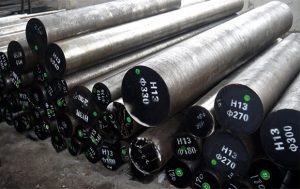
Image Credit: Taybro Alloys Stainless Steel Carbon is the most important component in commercial steel alloy. Increasing carbon content increases hardness and strength and improves hardenability. But carbon also increases brittleness and reduces weldability because of its tendency to form martensite.   While there are steels that have up to 2% carbon content, they are the exception. Most steel contains less than 0.35% carbon. Now, any steel in the 0.35% to 1.86% carbon content range can be hardened using a heat-quench-temper cycle. Most commercial steels are classified into one of three groups: 1. Plain carbon steels 2. Low-alloy steels 3. High-alloy steels

1. Plain Carbon Steels

– These steels usually are iron with less than 1% carbon, plus small amounts of manganese, phosphorus, sulfur, and silicon. – The weldability and other characteristics of these steels are primarily a product of carbon content, although the alloying and residual elements do have a minor influence. Plain carbon steels are further subdivided into four groups: a. Low b. Medium c. High d. Very high a. Low Carbon Steel: Often called mild steels, low-carbon steels have less than 0.30% carbon and are the most commonly used grades. They machine and weld nicely and are more ductile than higher-carbon steels. b. Medium Carbon Steel: Medium-carbon steels have from 0.30% to 0.45% carbon. Increased carbon means increased hardness and tensile strength, decreased ductility, and more difficult machining. c. High Carbon Steel: With 0.45% to 0.75% carbon, these steels can be challenging to weld. Preheating, post-heating (to control cooling rate), and sometimes even heating during welding become necessary to produce acceptable welds and to control the mechanical properties of the steel after welding. d. Very High Carbon Steel: With up to 1.50% carbon content, very high-carbon steels are used for hard steel products such as metal cutting tools and truck springs. Like high-carbon steels, they require heat treating before, during, and after welding to maintain their mechanical properties.

2. Low-alloy Steels

When these steels are designed for welded applications, their carbon content is usually below 0.25% and often below 0.15%. Typical alloys include nickel, chromium, molybdenum, manganese, and silicon, which add strength at room temperatures and increase low-temperature notch toughness. These alloys can improve corrosion resistance and be responsive to heat treatment. But the alloys can make it crack susceptible, so it’s a good idea to use low-hydrogen welding processes with them. Preheating might also prove necessary.

3. High-alloy Steels

The stainless steel is the most important commercial high-alloy steel. Stainless steels are at least 12% chromium and many have high nickel contents. The three basic types of stainless are: a. Austenitic b. Ferritic c. Martensitic a. Ferritic: Ferritic stainless steels have 12% to 27% chromium with small amounts of austenite-forming alloys. b. Austenitic: Austenitic stainless steels offer excellent weldability, but austenite isn’t stable at room temperature. Consequently, specific alloys must be added to stabilize austenite. The most important austenite stabilizer is nickel, and others include carbon, manganese, and nitrogen. c. Martensitic: Martensitic stainless steels make up the cutlery grades. They have the least amount of chromium, offer high hardenability, and require both pre- and postheating when welding to prevent cracking in the heat-affected zone (HAZ).  

Steel Classification Systems

Before we look at the common steel classification systems, let’s consider one more high-carbon metal, cast iron. The carbon content of cast iron is 2.1% or more. There are four basic types of cast iron: 1. Gray cast iron , which is relatively soft. It’s easily machined and welded, and you’ll find it used for engine cylinder blocks, pipe, and machine tool structures. 2. White cast iron, which is hard, brittle, and not weldable. It has a compressive strength of more than 200,000 pounds per square inch (PSI), and when it’s annealed, it becomes malleable cast iron. 3. Malleable cast iron, which is annealed white cast iron. It can be welded, machined, is ductile, and offers good strength and shock resistance. 4. Ductile cast iron, which is often called nodular or spheroidal graphite cast iron. It gets this name because its carbon is in the shape of small spheres, not flakes. This makes it both ductile and malleable. It’s also weldable.

LNG

marine technology

Add Your Heading Text Here

Lubrication

Biological sewage treatment plant

Add Your Heading Text Here

Duties of crew after joining ship

ME protection system

UMS (Unattended Machinery Space) operation of ship engines

e Drawings

Deaerator

Add Your Heading Text Here

06 cam less hydraulic exhaust valve

Dead Man Alarm

Ramzan

chittagong shipbreaking

SCRUBBER SYSTEM AND MAINTENANCE

Under regulation 4 of MARPOL Annex VI the exhaust gas cleaning systems (scrubber) are excepted based on the criteria described on the guideline (resolution MEPC 259(68)). Wash water parameters limit was set for PH, PAH, Turbidity and Suspended particle maters and Nitrate.

To fulfil the specific requirements of the regulations three types of scrubber are being used which are generally designed to retrofit.

  • Open Loop
  • Closed Loop
  • Hybrid

General maintenance of the scrubber is usually same for all three types. Some additional maintenance for close loop and hybrid system is there.

Fig: Typical view of a scrubber


Main parts of the scrubber are

  • Seawater pumps (VFD operated)
  • Auto back flushing and bypass filters
  • Seawater analyzing unit
  • Seawater flowmeters
  • Seawater nozzles.
  • Exhaust extractor fan.
  • Exhaust gas analyzing unit
  • Wash water analyzing unit
  • Neutralizing agent dosing unit.

Seawater pumps (VFD operated)

Seawater pumps are generally VFD (Variable frequency drive) operated to give a constant flow during a load change. Pumps are designed to provide high flow to wash exhaust gas perfectly. General maintenance like seawater pumps needs to do. The attached seawater strainer needs to clean periodically. MGPS system for dedicated sea chest needs to maintain properly.

Auto back flushing and bypass filters

After the pump, seawater passes through an Auto backwashing filter to protect scrubber nozzles from being chocked. When the differential pressure of the filter increases it automatically back flushes without hampering the scrubber operation. Periodically need to clean the filter and back flushing motor can be overloaded due to dirt clogging inside the filter.

Fig: Back Wash Filter

Sea water analyzing unit

After filter Sea water analyzing unit analyzes for pH, Turbidity and measure the seawater temperature. Sensors for pH and Turbidity are calibrated by shore technicians. Ship’s crew needs to validate the sensors usually in three months period.

Scrubber unit

Inside the scrubber Seawater sprays by specially designed nozzles to properly mix with exhaust gas. Exhaust gas from all the machineries come to a common manifold. In the manifold, there are to dampers, one for direct emission to atmosphere another damper opens to the scrubber. Seawater nozzles are placed in different places for proper wash out of the gas. Nozzles can be chocked by foreign particles. During inspection need to clean the nozzles if found choked.

The scrubber is an enclosed space. Enclosed space entry procedure to be followed before entering into the scrubber for maintenance.

 A bypass damper is fitted in one of the generator exhaust lines which will allow running the generator in case of any emergency.

Fig: View of sea water spraying nozzle


Exhaust extractor fan.

There is a VFD operated exhaust extractor fan that is placed on top of the scrubber to create a cyclone for better washing of gas and also pushing the exhaust gas to the atmosphere. Carefully need to keep eye on fan sealing as the seawater from inside can damage the windings of the fan motor. Motor bearings need to greased with special types of H.T grease.


Exhaust gas analyzing unit

Before released to the atmosphere Exhaust gas analyzing unit continuously monitor the gas for SO2, CO2, Sulphur and SO2/ CO2 ratio. If the Sulphur content increases the unit gives a signal to neutralizing agent injector pump regulator to inject alkaline chemicals to reduce the Sulphur content in the gas. Sensors are calibrated by shore technicians. Ship’s crew needs to validate the sensors usually in three months period.

Fig: View of a scrubber control monitor

Wash water analyzing unit

Wash water analyzing unit analyzes the water for pH, PAH, Turbidity and Suspended particle maters and Nitrate. A small vane sampling pump takes the wash water samples and passes it to the sensors. If the measured values cross the preset value it raises alarm. If the measured pH of the wash water lower than 3.5 it gives the signal to neutralizing agent dosing pump regulator to inject alkaline chemicals to increase the pH value of the discharged water. Sensors are calibrated by shore technicians. Ship’s crew needs to validate the sensors generally in three months period.

Neutralizing agents

Few neutralizing agents can improve the performance of the system. The commonly known agents are caustic soda (NaOH) or sodium carbonate (Na2co3) or magnesium oxide (MgO). These are generally received from the supplier  in liquid form.

Maintaining the chemicals improper state is very important. The chemicals are very temperature sensitive. It may be very catastrophic if the chemical temperature is not maintained within the prescribed temperature range. Proper chemical handling equipment’s to be used and PPE to be worn before handling the chemical.

Additional maintenance for closed-loop and hybrid system is there. Exhaust sludge residue tank and wash water collecting tanks need to maintain in proper condition. Exhaust sludge residue to be discharged to the shore facilities.

Scrubber log record

There is an official dedicated log record book for scrubber run-time parameters. Parameters to be recorded daily. All the scrubber related information also needs to be recorded such as neutralizing agent bunkering, non-compliance, incident related to the scrubber, sensors calibration reports, etc.

End of the day scrubber is a whole new type of machinery introduced in the marine industry. Ultimate care of this should be taken. Maintenance of this needs to be done carefully. Failing of the equipment/ lack of maintenance can end up in a huge financial loss for the owners.


References

  • Resolution MEPC.259(68)- 2015 Guidelines For Exhaust Gas Cleaning Systems- IMO
  • Technical Update 13-2014 / November – Preparing For Low Sulphur Operation-DNVGL
  • Prevention Of Pollution Of The Sea (Air) Regulations- MPA
  • Operation and maintenance manual CM.
  • imo.org
Dual Fuel Engine

DUEL FUEL ENGINE IN MARINE INDUSTRY AND IT’S ADVANTAGES & DISADVANTAGES

Author: Md Taifur Rahman, MEO-2, MPA, 46/E, BMA.

Dual fuel engines were introduced in the marine industry through the gas carriers. But now a day’s large size containers are also started to uses duel fuel engines. These engines use both natural gas and bunker fuel to meet the IMO and MARPOL regulations as its having cleaner-burning properties. Rapidly this engine is getting very popular in the maritime industry due to its higher cost benefits.

 Dual Fuel Engine


Dual Fuel Engine

Duel fuel engine works on compression ignition principle same like other marine engines. But here two types of fuel are used at the same time. Low-pressure natural gas is supplied to engine cylinder which gets mixed up with air and gets compressed as the piston reaches TDC. But this gaseous mixture of natural gas and air are not good at compression ignition. So small amount of diesel as a pilot fuel is injected to the cylinder to start the combustion process. The sudden injection of diesel can create a knocking problem which is controlled by the quantity of diesel being injected. In some engines, natural gas is compressed up to very high pressure (250-300 bars) before being supplied to the cylinder and then inject at the same time with pilot fuel. This is more efficient than providing gas to the cylinder earlier.

The amount of pilot fuel being injected is around 6% of the total load. But if natural gas supply becomes limited the amount of pilot fuel injection will vary to meet the changing engine load demand. If the natural gas supply is not available the engine will run on “fuel oil mode” only. This mode is used mostly on restricted water, heavy weather, maneuvering, etc.
Some leading duel fuel engine manufactures are caterpillar, MAN Diesel & Turbo, Wartsila, Hyundai, Rolls Royce, Yanmar, Cummins, ABC Diesel.

Some Safety features:
• Engine will continue to run on oil if natural gas is unavailable.
• Engine will use fuel oil during starting
• Run on Fuel oil mode in restricted water, heavy weather, maneuvering etc.
• Crankcase pressure relief valve fitted at both sides of the engine.
• Flame arrester at the air starting line of each unit
• Each unit gas supply valve to be equipped with a flame arrester.
• Independent Exhaust system

Advantages:
• Cleaner exhaust, environmentally sound.
• Less fuel is needed and natural gas is comparatively cheaper.
• Spark plug is not required.
• Engine can run on both gas and fuel oil.
• More efficient than diesel engine at higher load conditions.

Disadvantages:
• Fuel management measures are costly.
• Chances of gas leakage.
• Natural gas bunkering may not be available at all the ports.

BALLAST WATER MANAGEMENT

BWMS & BWTS

To prevent the introduction of harmful aquatic species into new environments by shipping which have been thought to be a major threat to marine ecology and have been devastating in many areas of the IMO adopted the Ballast Water Management Convention in 2004 at a diplomatic conference in London and eventually the convention entered into force on 17th September 2017.

More than 65 states representing more than 70% of the total world tonnage signed the BWM Convention

Continue reading

Nitrogen Gas genereator

NITROGEN GAS GENERATOR

Ship’s Nitrogen Gas Generator

Nitrogen gas  generators are used to produce clean and dry nitrogen of higher purity for inerting, purging and cargo padding.

Mainly there are two types of nitrogen generators are widely used on board:

  • One type uses hollow fiber membrane technology and
  • Other one is based on the Pressure Swing Absorption (PSA) process.

Nitrogen may also be supplied from ashore in nitrogen cylinders and stored on board, but nitrogen generators are most convenient way for inerting, purging and cargo padding.

Requirement of nitrogen used as inert gas on chemical tankers:

On tankers nitrogen is not used for fighting fire but for cargo quality control.

Some cargoes are very much oxygen sensitive to react with and may turn to out of specification. Some cargo may also react with carbon di oxide in the flue gas. Other cargoes are highly sensitive to moisture and may liable to discoloration. The cargoes require inert gas of extreme purity to exclude oxygen from the tanks.

Oil fired flue gas contains less oxygen but at the same time it contains soots and carbon di oxide which may react with cargoes. For these reasons oil fired flue gas systems are rarely used on chemical carriers.

Inerting:

The introduction of inert gas into a tank with the object of attaining the inert condition.

Purging:

 The introduction of inert gas into a tank already in the inert condition with the object of:

(1) further reducing the existing oxygen content; and/or

(2) reducing the existing hydrocarbon gas content to a level

Topping up: The introduction of inert gas into a tank which is already in the inert condition with the object of raising the tank pressure to prevent any ingress of air.                                                                      

Nitrogen generator can be operated in two modes, based on purity

  • 95% purity
  • 99.9% purity

Nitrogen generator can also be operated on fresh air mode where it supplies air from the atmosphere to the cargo tanks.

Components of N2 generator:

Air compressor unit: It consists of a number of motor-driven screw compressors. This compressor unit must be supplied with the cooling arrangement.

Air dryer: It removes moisture from the compressed air. To ensure proper functioning of the separating unit moisture must be drained out.

Air filter unit: This unit consists of air filter and an activated carbon tower. The air filter separates oil and impure substances from the air delivered by the air compressor. It may also be fitted with auto drain to facilitate drainage. Sometimes additionally an air heater is also fitted. This is of vital importance to remove oil from the air to protect the carbon molecular sieve or membranes. The activated carbon tower prevents any oil, moisture, and foreign material to enter the PSA unit in the event of malfunction of air dryer and air filter units.

PSA (Pressure swing adsorption unit):

The adsorbent packed in the adsorption tank selectively adsorbs oxygen gas under the pressurized condition and separates nitrogen gas.

Adsorption is a process in which a substance accumulates on the surface of a solid to form a very thin film. The principle of oxygen separation is that the major constituents of air (nitrogen and oxygen) are adsorbed to a different extent when passed over a carbon-molecular sieve material. 


The sieve adsorbs most of the oxygen from the air, allowing the nitrogen to pass through and be collected. The oxygen is desorbed and vented to atmosphere.  The carbon-molecular sieve material also adsorbs a number of other gases, i.e.: carbon dioxide and water vapor.

Buffer tank is provided to ensure constant flow of pure nitrogen gas throughout the operation.


   The cycle of adsorption, desorption and filling is repeated by every minute to produce nitrogen gas continuously.

 Membrane unit:

Selective permeation is the basic principle of gas separation by membrane modules. Permeation of a gas is the ability to dissolve and diffuse through a membrane. Gases are separated as their permeability. Gases with higher diffusion rate and lower molecular sizes can penetrate the membranes faster than gases with larger molecular size and lesser diffusion rate.

 The ‘slow’ gases are methane, nitrogen and carbon monoxide, the ‘medium’ gases are argon and oxygen, and the ‘fast’ gases are water vapour, hydrogen and carbon dioxide. O2, H2O, CO2

The “fast” gases, permeate through the membrane wall much faster than the “slow” gases, thus separating the original mixture into two streams.

The membrane unit is made up from bundles of thin hollow fibers which give a large wall area for separation.  Each membrane module contains millions of hollow fibers. The membrane bundles are enclosed in pressure vessel pipes of about 100 to 200 millimeters diameter; several of these bundles may be arranged in parallel.

As the two main components of air are nitrogen and oxygen and they have different permeation rates means they can be separated by membranes once they pass through.

Hence the high velocity gases pass through the membranes and vented to atmosphere allowing only nitrogen to come out from the membranes.

An oxygen sensor is fitted at the outlet of purified product gas that indicates the level of purity. i.e. oxygen content. When the oxygen level comes down to desired level it allows pure nitrogen gas to pass to the deck and close the vent valve leading to atmosphere. The efficiency of the separation depends on the flow rate through the membranes; a control valve is used to regulate the flow and thereby the oxygen content. Oxygen enriched air is vented as a waste gas, which must be exhausted to a safe area. To ensure reliability of the measured values oxygen analyser needs periodic calibration. AIR point calibration is sufficient when using for tasks such as measuring oxygen concentration in an inert gas which does not contain a degrading gas. SPAN point calibration needs if the sensor has been degraded or the sensor unit has been replaced.

ISOLATED AND EARTHED NEUTRAL SYSTEM

Author: Usman Karneh

The function of an electrical system is to safely convey the power from the point of generation (source) to where it is required the various loads or equipment connected to it. The electrical source, like the load may either be a single phase (2-wire) or three phase (3 to 4- wire) system


An electrical system can take any of two forms:
Neutral Insulated system, or
Neutral Earthed system.
For single phase neutral insulated system, the neutral of the source is insulated. In other words, the neutral is not connected to the earth. While for the neutral earthed system, the neutral of the source is connected to the earth.
For three phase star neutral insulated system, the common point of the source is not connected to earth. Hence there are only 3 phase wires R,Y,B emerging from the source. In neutral earthed system, the star point is earthed to ground. So 4 wires emanate from source (3 phase and 1 neutral).

Three (3) types of fault may occur in an electrical system:
Open circuit fault: is the result of a break in the conductor so that no current flow through the load.
Short circuit fault: is due to break in insulation and two conductors (line and neutral) are directly touching each other resulting into a short path to current flow and allowing a very large current to bypass the load.
Earth Fault: This is also due to insulation breakdown which somehow allow the conductor to come into direct contact with the metal enclosure or body frame of the equipment.
A single earth fault occurring in the line of an earthed neutral system, would be equivalent to a short circuit fault since this will creates a closed path for the earth current to flow through to the ground as a result of minimal resistance, this earth current may increase to a very large extent. If the earth current increases beyond the current rating of the generator, the entire system may collapse causing irreparable damage. To limit this earth current, a Neutral Earthing Resistor is connected to the earthed neutral of the source. This resistor is of sufficient ohmic value to limit the earth current within rating of the generator. However, the magnitude of earth current is sufficiently large to operate the tripping mechanism of the faulted equipment immediately isolating it from supply and rendering it safe.
A single earth fault in a neutral insulated system, would not cause any earth current to flow. This is because a single earth fault current does not provide a complete circuit for earth current to flow. So no protective trip will operate and system will continue to function normally.
However, if a second earth fault occurs on another line in the insulated system, the two earth faults together will be equivalent to a short circuit and the resulting earth fault current will operate the available protection devices and cause disconnection of services.
For system where the priority requirement is to maintain continuity of the electrical supply to essential equipment in event of a single earth fault occurring the isolated neutral (neutral insulated) system is used. For system where the priority requirement is the immediate isolation of earth-faulted equipment is automatically achieved by a neutral earthed system.

To understand this better, a case study is used; If the earth fault occurs in an essential system like that of steering gear of a ship, then in case of: Insulated neutral system, no earth fault current will flow and the steering gear will continue to operate until there is a second earth fault in any equipment present onboard. Hence, with a single earth fault, the essential service will continue to operate.
If the system would have been an earthed neutral, then a single earth fault would have caused heavy earth current to flow and operate the tripping mechanism causing shutting down of steering gear. This will seriously compromise the safety of the ship navigation. Hence, it is well understood that onboard a ship, a neutral insulated system is to be used while, in an industry or on shore installations neutral earthed system is used.
Shipboard main LV systems at 440 V are normally provided with neutral insulated system. On the other hand HV system (1000 V to 3.3 KV) are usually provided with neutral earthed system via a neutral earthing resistor.
In a HV system, certain essential loads can be supplied by a transformer with it’s secondary insulated to ensure no earth fault current flows in the equipment in order to maintains the continuity of service.

Shipping regulations require that the hazardous areas of tanker such as the cargo area, pump room should have a neutral insulated system to prevent any stray earth current from flowing in the hull and causing explosion hazard.
However an exception is included in case if tanker has a 3.3 KV system, the earthed system is permitted provided that the earthed system does not extend forward of engine room bulkhead and into the hazardous area.

Both the Insulated neutral and Earthed neutral system have got their own advantages and disadvantages. Where it is easier in the earthed neutral system to detect any earth faults in system, it is easier in isolated neutral system to maintain the continuity of service.

ACCIDENTAL AGROUNDING: CHIEF ENGINEER’S RESPONSIBILITY

Once a vessel has grounded there are a number of considerations that need to be addressed:

  • Has the hull of the vessel been broached during grounding. Sounding all the various tanks that are situated behind the outer hull can check this. If the hull has been broached, then the vessel should not be refloated unless it is determined that sufficient buoyancy and stability remains once the vessel is floating freely.
  • Has the hull of the vessel been deformed in any way. This could lead to increased bearing loads on the main engine and/or main transmission shafting
  • Has the propeller or rudder become fouled or damaged. Ensuring both units are free to rotate without any excess loads could check this.
  • Is the vessel discharging any oil. A check on the tank levels may assist in locating possible damage, but any external pollution should be controlled as soon as practical.
  • Are the sea suction intakes blocked/covered by the seabed. Any reduction in the seawater pressure could require that the sea suctions be changed over.

 Soundings around the vessel should take place to determine where the vessel has grounded, and the type of seabed on which the vessel is laid.

Once the vessel has been grounded there should be an estimate of when the vessel may be re-floated. This could depend on the local tides, vessel loading condition, and vessel ballast condition. If the vessel were fully loaded, then discharge of the cargo may take a number of days, then it may be prudent to reduce the services supplied by the engine room. This will reduce the fuel consumption whilst aground. The limit of services may be dictated by any possible damage to the vessel’s hull.

One area of concern may be that the if the engine were normally operating on residual fuel, then to keep the fuel injection system warm this has to be circulated at all times. Should a fuel injector be leaking, then this could cause a build-up of fuel on top of the piston, which will cause excessive pressure rises when the engine has started. Thus the main engine should be changed over to diesel oil. This change over must avoid high rates of temperature changes, and once fully flushed the fuel oil system can be shutdown until the main engine is required again.


Once the vessel has been re-floated, then the following inspections should take place:

  • An in-water survey should be carried out with the agreement of the Classification Society. This will require that the vessel be in clear water, so that divers can examine the underwater portion of the hull. They will examine all hull plating, looking for dents, holes, etc.
  • A function test of the rudder and transmission shafting
  • A full set of crankshaft deflections should be taken. The readings obtained should be compared with previous readings, and also be within the engine manufacturer’s recommendations for that engine. Whilst measuring the deflections, bridge gauge readings may also be taken to ensure that the crankshaft is sitting firmly on the lower bearing half.
  • Even though the divers are examining the external hull shell plate, it may also be prudent to examine the cofferdam in way of the main engine seating, to ensure that the full strength of this important seating area is intact before engine power is resumed.

CHECKING PERFORMANCE OF MAIN ENGINE

In order to monitor the engine performance, we would need to measure the power output and fuel consumption of the engine. This will allow the performance of the engine to be measured against previous and even test bed readings.

The staff would be instructed to the followings:

  • Measure the power of the each cylinder by electronic pressure measurement. If the engine was driving an electrical load, then the electrical output power could be used. This will allow the total engine power to be calculated, and also for any power imbalance to be detected. This power measurement would be taken every month.
  • Measure the fuel consumption of the engine every day over a 8 and 24 hour period. This consumption would be measured in tonne/hour, and thermal and density conversions from a volumetric flow rate at the meter would be required.
  • Calculate the specific fuel consumption of the engine in terms of g/kWh, so that fuel consumption at various engine conditions could be compared.

Engine room staff would be instructed to the followings:

  • Closely monitor the pressure differential across the lube oil filters each day, and to report any increase in this pressure, or the frequency of automatic filter blowdown.
  • Take a representative sample from the lube oil inlet to the engine every week.
  • This sample would be tested on board for
  • Water content
  • Change in viscosity
  • BN reserve
  • In addition every month a representative sample would be taken and sent for shore analysis so that a wider range of variables could be analysed.

The general condition of the engine could be monitored by measuring the various parameters taken by the data logger or manual log readings.

The staff would be instructed to the followings:

  • Take a full set of readings twice a day on all the major parameters of the engine, such as
  • Exhaust gas temperatures
  • Lube oil pressure and temperature
  • Fresh water cooling pressure and temperature
  • Scavenge air pressure and temperature
  • T/C rev/min
  • Exhaust gas smoke levels
  • These readings would form the basis of the datum readings for that engine, and any major changes to the measurements should be reported to the Chief Engineers without delay.
  • In addition, should electronic power measurement not be available on-board, then peak pressure readings of each cylinder would be taken monthly to ensure even loading of the cylinders

ISOLATION OF ONE UNIT OF MAIN ENGINE

One unit may need to be disabled when any of these conditions exist:

  • Damage to a main component of the combustion chamber
  • Damage to a crosshead or bottom end bearing on that cylinder

The following sequence would be carried out for our vessels which use the MAN B&W slow speed engine:

  • Stop engine, isolate systems and allow to cool
  • Ensure a procedure is written that minimises the risk to personnel during the operation. Discuss the task and written procedure with the engine room personnel to ensure they are familiar with the risks, and the methods to be used to minimise these risks.
  • Ensure the fuel pump is de-activated by lifting roller and locking.
  • Lift exhaust valve actuators so exhaust valve remains closed during running (Note: the air spring supply to be left open)
  • Dismantle air start supply line, and blank with suitable steel plates, the main and control air pipes
  • Dismantle bottom end bearing, and turn engine to suspend piston, crosshead and connecting rod from supplied crosshead supports. Secure big end of connecting rod in crankcase.
  • Blank off main oil inlet to crosshead within the crankcase with a blanking plate
  • Isolate the cylinder lubricator for that cylinder by placing all lubricators on no stroke.

When one engine cylinder is isolated, then one problem that may occur is a “dead spot” during manoeuvring.

This is due to the air start valve being isolated for that unit, and is more likely when a smaller number of cylinders are present. The Master must be informed that this could occur, and the remedy would be to kick the engine in the opposite direction, and then restart in the required direction.