1.0 Fuel and Lubricants
1.
Draw a line diagram of a simple distillation process indicating the points at which kerosene, gas oil, residual fuel, heavy gas oil and lubricating oil are fractioned off. (10)
2.
(a) What are the reasons for the deterioration in the quality of fuel supplied for use in marine diesel engines.(2)
(b)Write short notes on the following fuel characteristics, Viscosity, Density, CCAI and Calorific value (8)
3.
(a)Explain upper and lower flammable limit of hydrocarbon using a graph (7)
(b) Define classification of dangerous fuels by their flash point.(3)
4.
With respect to fuel characteristic used in internal combustion engines
- Define ignition delay.(2)
- Explain octane number and cetane number (8)
5.
(a)Describe the source of water contamination of fuel.(3)
(b) Describe the on board testing procedure for water in fuel (4)
(c) Discuss the effect of salt water contamination of fuel oil on engine.(3)
6.
(a) What are the likely consequences if fuel with excessive catalytic fines is used in an engine.(8)
(b) What adjustment is required to remove this catalytic fines are more efficiently removed in separators. (2)
7.
(a) Why fuel oil additives being used in fuel oil (4)
(b) Explain the harmful effect of having excessive sulphur, vanadium and catalytic fine in bunker fuel. (6)
8.
(a) Draw and describe a oil filter module capable of removing water.(7)
(b) Describe the automatic back flushing process of the module.(3)
9.
Write down the key check points and documentation required in different stages of bunkering , (a) Before bunker (2)
(b) During bunker (6)
(c) after bunker (2)
10.
(a) Explain the difference in use of the fine mesh filter with respect to coarse types. (2)
(b) Draw a Auto-Klean filter and describe the cleaning process including the particle size it is capable of filtering out. (8)
11.
State the precautions to be taken against spillage during bunkering operations. ( 10)
12.
With reference to the treatment of lubricating or fuel oil:
a.State the function of a purifier;(2)
b.State the function of a clarifier;(2)
c.State TWO constructional differences found in the bowls of purifiers and clarifiers (6)
2.0 Pumps and pumping system
1.
(a) Sketch a lubricating oil pump and explain it’s operational procedure.(6)
(b) Identify the clearances critical to pump efficiency (2)
(c) Why a relief valve is needed? (2)
2.
(a) Sketch a centrifugal pump (5)
(b) Why such a pump may require a priming pump? (3)
(c) State two distinct characteristics that separates it from other pumps. (2)
3.
(a) Sketch a pump most suitable for lub oil circulation in a marine engine. (6)
(b) What is the function of the timing gear? (2)
(c) How axial thrust is managed with in acceptable limit in such a pump (2)
4.
(a) Draw and describe a constant speed, unidirectional, variable stroke, axial flow, rotary positive displacement pump.(8)
(b) State 2 shipboard application of such a pump (2)
5.
With reference to self priming centrifugal pumps
(a) Sketch a liquid ring priming pump and describe how it operates? (7)
(b) Why all ER centrifugal pumps are not fitted with priming pump?(3)
6.
(a) Draw a line diagram of central priming system, label the principal items and show the flow in all lines.(6)
(b) State the advantages and disadvantages the system has over individual priming equipment (4)
7.
With respect to centrifugal sea water pumps
(a) Give four reasons why the output may reduce (6)
(b) If the pump vibrates occasionally, what could be the causes? (4)
8.
(a) Explain with suitable graph following characteristics of a centrifugal pump VS quantity delivered. A) Discharge head b) NPSH c) input Power d) Efficiency (10)
9.
(a) Draw and describe a pump suitable for noxious chemical cargo discharge (7)
(b) State the need for two seals and the use of cofferdam between seals (3)
10.
(a) Sketch a double acting reciprocating pump with suitable valve assembly.(6)
(b) Describe the operation including the use of an accumulator. (4)
11.
With reference to Diesel engine driven emergency fire pumps
(a) Define their limitation as regards to suction lift, out put and jet distance (5)
(b) Explain how and why they are isolated from the main fire pumps (3)
(c) State two suitable locations for such a pump. (2)
12.
(a) Sketch and describe a centrifugal pump.(4)
(b) Why Relief valve is not fitted in above pump?(2)
(c) Identify the causes of cavitation in centrifugal pump.(4)
13.
(a) Sketch and describe a pump other than a centrifugal pump.(4)
(b) Why positive displacement pump is required relief valve but centrifugal pump doesn’t require?(3)
(c) Centrifugal pump taking not taking suction, state three main reasons.(3)
14.
With respect to centrifugal pumps describe causes of followings.
(a)Pump not taking suction.(3)
(b)Pump fails to deliver liquid.(3)
(c)Pump doesn’t deliver at rated capacity.(4)
15.
With reference to centrifugal pumps:
(a) explain why large pumps should be started with the discharge valve closed; (6)
(b) state FOUR possible reasons for failing to achieve suction from a double bottom tank.(4)
16.
With reference to a steam heating coil in a fuel storage tank developing a leak:
a.State how the leak would be detected;(3)
b.State the immediate action to be taken when the leak is detected;(3)
c.Explain how the leak may be traced.(3)
17.
a.Describe, with the aid of a sketch, the bilge injection system (6)
b.State the purpose of fitting a bilge injection system on board a ship (4)
18.
a.Outline the separation process that occurs within centrifugal oil purifiers (5)
b.Describe the change required to the purifier if it is to be used for an oil of lower density(5)
19.
a.Outline the separation process that occurs within centrifugal oil purifiers (5)
b.Describe the change required to the purifier if it is to be used for an oil of very low quality and high density (5)
20.
List EIGHT reasons why a bilge pump may not be able to remove water from an engine room bilge.(10)
21.
With reference to centrifugal purifiers:
state the function of the gravity disc; explain the consequences of EACH of the following:
(i) gravity disc too large (5)
(ii) gravity disc too small (5)
3.0 Heat Exchangers
1.
With reference to multi tubular sea water coolers
(a) Sketch a two pass cooler showing the direction of fluid flow (5)
(b) Give two faults to which it is prone and how these faults are countered (5)
2.
With reference to multi tubular oil coolers describe
(a) Indications of tube leakage and locating procedure by tests. (6)
(b) temporaray and permanent corrective steps to stop leakage (4)
3.
(a) Explain how the following conditions contribute to the satisfactory performance of multi tubular heat exchangers, i) Low tube thickness ii) cross flow iii) Baffle plates (6)
(b) Why it is of utmost importance that the division plate is intact and anodes are secured properly. (4)
4.
(a) Describe with the aid of a diagram how a sea water circulatory system is subjected to electrical current at a controlled rate.(7)
(b) State how in such a system the valves, pipes and coolers are protected. (3)
5.
(a) Sketch a plate type heat exchanger showing the sealing arrangements and flow directions. (6)
(b) State the advantages and disadvantages of plate type heat exchanger over tube type. (4)
6.With reference to plate type heat exchangers, state why
(a) the plates carry a relief pattern (4)
(b) The carrying bars and clamping bolts are far longer than appears to be
Necessary (3)
(c) Pressure and temperature of fluids handled are restricted (3)
7.
With reference to evaporators and distillers
(a) Describe the function of demister.(2)
(b) Describe, with the aid of simple sketch, a low pressure evaporator which uses engines heating medium.(8)
8.
(a) What is osmosis and reverse osmosis? (3)
(b) Describe with sketch, Reverse osmosis process. (7)
9.
With reference to evaporators and distillers
(a) Explain why low pressure evaporators are used? (3)
(b) Explain what is meant by single effect and double effect evaporation?(3)
(c) Describe, with the aid of simple sketch, a two stage flash evaporator.(4)
10.
(a) With the aid of diagram explain the working principle of a Evaporation type fresh water Generator.(6)
(b) Why is it suggested not to drink the generated distillate water and when it is safe to use? (4)
11.
- a) Draw a line diagram of a central cooling system installed in cargo ship with the principle components and showing the direction of flow in all lines. (3)
- b) Explain the function of this arrangement.(3)
- c) Give two advantages and two disadvantage of this system compared to the practice of employing central cooling system for each service.(4)
12.
- a) What is the function of wear ring? (4)
- b) Draw a line diagram of central cooling system and explain its advantages and disadvantages.(6)
13.
With reference to centrifugal separator
- a) Differentiate between the purpose and operation of purifier and clarifier.(2)
- b) Explain how these different roles are achieved? (4)
- c) What are the factors need to be maintained for good purification process?(4)
14.
- a) Explain the hazard of maintaining low quality of engine system oil in circulation.(3)
- b) If on passage you had reason to think that the lubricating oil in the main engine was contaminated, Can you state any checks which would help you come to a conclusion about the contamination. (7)
15.
- a) Describe the regular systematic inspection of main air compressor, reservoir and accessories.(5)
- b) Identify common faults to which compressors and reservoirs are susceptible.(2)
- c) Describe how these faults are prevented and rectified?(3)
4.0 Steering Gear
1.
(a) Explain the function of a hydraulic telemotor with the aid of a sketch. (5)
(b) Explain the charging system of the unit.(3)
(c) State how air in the system is detected and removed.(2)
2.
(a) Draw a line diagram of the hydraulic system for a Ram Steering gear, labelling the principal items (6)
(b) Describe how the cushioning and relief arrangements function.( 4)
3.
With reference to ram steering gears explain
(a) the purpose of rapson slide and the mechanical advantage achieved (5)
(b) How a four ram gear can be operated with two rams in four combinations (5)
4.
(a) Sketch a hunting gear as fitted to a hydraulic steering gear, label it and explain how it works both normally and in adverse weather condition.(7)
(b) Explain why relief valves are provided as well as shock valves in hydraulic steering gears. (3)
5.
With reference to steering gears explain:
(a) Explain with diagram how Rudder is supported by the rudder carrier bearing and how the conical shape of the bearing helps.(7)
(b) How limited amount of rudder drop is accommodated.(3)
6.
With reference to hydraulic steering gears, explain why:
(a) Telemotor receivers are spring loaded (5)
(b) Rudder movement is confined by the stops in the control systems(5)
7.
(a) Sketch a rotary vane steering gear and explain how it operates (7)
(b) Explain the advantages and disadvantages it possesses over Ram type.(3)
8.
(a) Describe the major rules and regulations regarding steering gear and how single failure criteria rule is implemented. (8)
(b) State the difference between ‘follow up’ and ‘non follow up’ operation.(2)
9.
(a) Sketch a ward-Leonard all electrical steering system and explain how it works.(8)
(b) In case of unintentional rudder movement due to weather is corrected (2)
- a) Describe with simple sketch, the principle of operation of axial piston pump used in steering gear. (5)
- b) Describe with the aid of simple sketch, how the pump is controlled to move the rudder from one position to other. (5)
11.
- a) Regarding steering gear what are the regulations extracts from SOLAS convention?(4)
- b) What do you mean by “FOLLOW UP” system?(3)
- c) What do you mean by “NON-FOLLOW UP” system?(3)
12.
- a) Sketch a hydraulic circuit of a two ram steering gear system mentioning the shock relief and direction of flow for clockwise rotation of the rudder stock.(4)
- b) Explain the advantages of “Rapson slide mechanism” incorporated in steering gear system.(2)
- c) Explain why excessive wear down of rudder carrier bearing is dangerous in ram type steering gear? (2)
- d) Explain how shocks to the system from wave action on rudder are absolved?(2)
13.
- a) Draw a rotary vane steering gear? (4)
- b) How does it work?(4)
- c) Write one advantage and one disadvantage of ram type steering gear. (2)
14.
- a) Sketch a hunting gear as fitted to a hydraulic steering gear labeling the principle items. (6)
- b) Explain the purpose of hunting gear.(4)
15.
Describe the procedure for testing a steering gear within 12 hours of sailing.(10)
16.
With reference to the testing of a ship’s steering gear, prior to departure, list EIGHT items of machinery or control systems whose operation must be tested (10)
5.0 Oily Water Seperator/Sewage treatment plant/Ballast water Treatment Plant/Scubber system
1.
With reference to oily water separators
- Sketch and describe the operation of a two stage OWS.(6)
- What is the principal of separation and how preheating is beneficial.(2)
- What is the effect of varying degree of through put.(2)
2.
With reference to OWS
(a) Outline the routine attention needed to maintain satisfactory performance.(6)
(b) Define theadverse effect of cleaning chemical and turbulant flow in the performance(4)
3.
With reference to oily water separators explain why:
(a) Internal baffles are commonly fitted
(b) Coalescers are generally incorporated.
4.
Give reasons why each of the following conditions can result in bad performance of the OWS,
(2.5 X 4)
- i) high oil density
- ii) high throughput
iii) turbulance and
- iv) cleaning chemical
5.
(a) Sketch a 15ppm monitoring device fitted to Oily water separator discharge line and explain it’s operation.(6)
(b) State the conditions that needs to be fulfilled before the operation of an approved OWS.(4)
6.
With reference to oil content monitoring and control system:
(a) Explain with a sketch the operation of oil content monitoring system as fitted to the oil tankers.(7)
(b) What are the signals at the calculating unit that is recorded.(3)
7.
(a) Sketch and describe the operation of a Biological Sewage treatment plant.(7)
(b) Define ‘BOD’ and ‘Colifor count’ (3)
8.
(a)Sketch and describe how a ‘zero discharge’ sewage treatment plant works. (6)
(b) Write the Marpol annex IV rules regarding discharge of sewage from ships(4)
9.
- a) With the aid of sketch, Describe vacuum sewage system.(5)
- b) State three advantages possessed by vacuum sewage system.(3)
- c) Explain the term “coliform count”.(2)
10.
- a) In oily separator, what type of pump is used, why centrifugal pump is not in use?(3)
- b) What are the forces available in OWS? (2)
- c) What are the safeties provided in OWS? (5)
11.
- a) Describe with the aid of sketch, an aerobic STP. (5)
- b) State the effect of, in any change in temperature and regularity of flow on the system.(3)
- c) Explain the significance of Biological Oxygen Demand (BOD) (2)
12.
- a) Describe working principle of OWS.(3)
- b) Give two reason why oil might be carried over with the water from an OWS? (2)
- c) Outline the routine attention needed to maintain satisfactory performance of an OWS. (2)
- d) Define the contribution of test cocks towards functional efficiency.(3)
13.
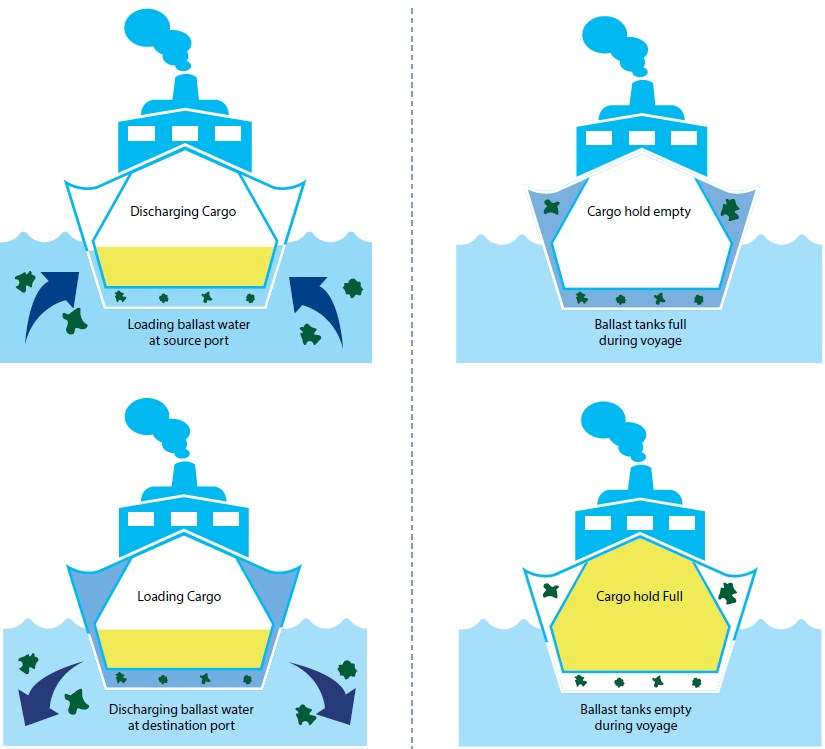
Write presently available ballast water treatment systems. Describe any one Ballast Water Treatment System with appropriate drawing.
14.
(a) What is SCR( Selective Catalytic Reduction)?
(b) Draw and label a SCR and briefly explain how it works.
15.
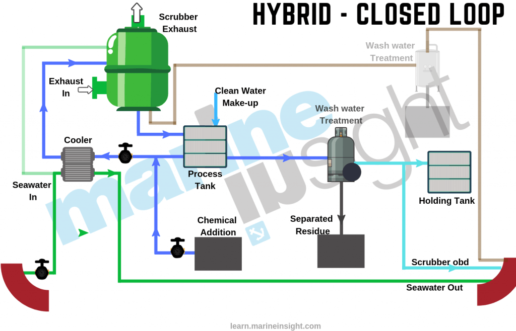
(a) How Sox is produced on board the ship? What is the present regulation? (b) Draw a Sox scrubber plant and explain briefly.
16.
(a) With the help of diagram, describe in brief a biological type sewage treatment system.
(b) Why chlorination is necessary in this system?
27.
- Describe the procedure for operating the oily water separator (5)
- State TWO ways that the separator could be made to operate more efficiently (5)
7.0 Shafting System
1.
With reference to the thrust blocks state why,
(a) cooling coils are sometimes fitted in the sumps (3)
(b) axial clearance between collar and pads is minimal (4)
(c) They occasionally overheat (3)
2.
With reference to main thrust blocks:
(a) identify the critical clearances and state why they are critical.(3)
(b) describe with sketches how these clearances are adjusted.(4)
(c) give reasons why such bearings sometimes overheat although the clearances are adequate (3)
3.
With reference to the transmission shaft coupling bolts state:
(a) why they are made a drive fit in the coupling holes.(3)
(b) why they are tightened to the limit of elasticity.(3)
(c) how couplings are assembled using “interference fit” boards.(4)
4.
With reference to the transmission shaft coupling bolts
(a) explain the conditions that causes fretting of main transmission shaft coupling bolts.(5)
(b) sketch and describe pilgrim bolt.( 5)
5.
With reference to propeller shaft couplings
(a) sketch and describe a coupling enabling external withdrawal of propeller shafts (7)
(b) state the advantages and disadvantages of this coupling compared to the solid flange coupling.(3)
6.
With reference to the transmission shaft bearings:
(a) sketch a bearing carrying large diameter main transmission shafting and explain how the bearing is lubricated and cooled.(7)
(b) give two reasons why such bearings occasionally overheat.(3)
7.
With reference to the stern tube sealing arrangements:
(a) sketch a sealing arrangement for an oil lubricated stern tube (aft) and explain how it
Works (6)
(b) state how oil loss due to seal failure can be restricted (4)
8.
With reference to the stern tube:
(a) draw an oil lubricated stern tube showing the seals forward and aft as well as the
bearings.(10)
9.
- a) Draw and describe intermediate shaft and shaft bearing.
- b) Suggest with reasons what remedial action should be taken upon arrival in port in case of suspected uneven load on the shaft .
- c) State the indications whilst at sea, that unequal loading of such bearing exist.
10.
State with a line diagram of two header tanks arrangement for the inboard oil seal and the direction of oil circulation.
11.
(a) What are the purposes of putting a thrust bearing between the main engine and propeller?
(b) How is the thrust bearing cooled?
(c) Explain how does a variable pitch propeller operate?
(d) Describe how does the fail safe feature operate in controllable pitch propeller?
12.
- a) Draw an oil sealing arrangement for stern tube aft and fwd seal.
- b) Compare the advantages of above with water lubrication one.
13.
With reference to keyless propeller explain
(a) Why keys and keys ways have been eliminated?
(b) How is angular slip avoided?
(c) Draw & explain muff coupling.
14.
a.Describe the actions that the EOOW should take on finding that the temperature of the thrust block is rising above normal acceptable range.(6)
b.Explain why the thrust block temperature is critical.(4)
8.0 Fire and Safety
1.
(a) Sketch a portable fire extinguisher suitable for oil fire, showing details of its triggering mechanism, chemical composition and the details of hose. (7)
(b) Describe the strength and limitation of this extinguisher (3)
2.
In shipboard fire detection system, state
(a) Draw and describe an Ionisation type smoke detector (6)
(b) How tests are carried out on the different types of sensor heads (4)
3.
In shipboard fire detection system
(a) Use a suitable sketch to explain, how immediate warning is given in a sudden conflagration and how a slow burning fire is detected.(8)
(b) Explain how false alarms can arise in (2)
4.
State why precautionary measures need to be taken in the following instances
(a) Entry into confined spaces, for example duct keel (4)
(b) Working in refrigerated spaces (3)
(c) Working in an emergency battery room (3)
5.
(a) Sketch and label a self contained breathing apparatus(4)
(b) State the precautionary measures taken on the SCBA set before entry into a confined space (3)
(c ) State the safety feature of SCBA to warn wearer of low air pressure (3)
6.
With regards to bulk CO2 Fixed fire extingushing system
(a) Sketch a layout for a typical shipboard application. (4)
(b) State regulations that control capacity, quantity, and duration of discharge (3)
(c) State the advantage and limitations with battery CO2 system. (3)
7.
Concerning the CO2 total flooding fixed fire fighting installation:
(a) What checks would be made before operating the system (3)
(b) Draw a line diagram and explain the releasing operation.(5)
(c ) After discharge, how soon could re-entry be attempted (2)
8.
With regards to emergency fire pump
(a) What factors influence the location, operation and power requirements (3)
(b) Draw a fire main system and state the location of isolating valve and emergency fire pump.(5)
(c ) Why drains are necessary on the deck main (2)
9.
(a) Sketch a sprinkler system state why it is considered as a detection and extingushing combination system. (6)
(b) After such a system has been activated, how would it again be made ready for service? (4)
10.
Make a comparision of the benefits and limitations of the following installations for shipboard machinery spaces.(10)
(a) High pressure water spray system
(b) CO2 total flooding system
(c ) Fixed foam smothering system
11.
(a) Sketch a fire detection control system and describe the main features (5)
(b) Sketch the switching mechanism to isolate air and fuel system powers before gang release of CO2. Narrate its operation.(5)
12.
Compare with reasons the merits and demerits of the following permanent fire extinguisher installed in machinery spaces
- a) High pressure water spray
- b) Carbon dioxide smothering
- c) Chemical foam smothering
13.
State with reason, two types of fire extinguisher that may be used to fight a fire in each of the following shipboard areas
- a) Galley
- b) Accommodation space
- c) Machinery space control room
- d) Main electrical switchboard
- e) Paint locker.
14.
With reference to entry of personnel into enclosed spaces
- a) State what minimum oxygen content in atmosphere within a space could be considered safe.
- b) Explain with the aid of sketch, the operation of an oxygen meter suitable for checking the atmosphere within an enclosed space.
- c) Explain the procedures to check the accuracy of the meter.
15.
- a) How tests are carried out on the different types of sensor head?
- b) Why mixed types of sensor are preferable in the engine room?
16.
State the safety checks needed before using EACH of the following lifting gear, assuming that all certificates are in order and the equipment load capacity is sufficient for the lift:
a.wire strops;(5)
b.chain blocks;(5)
17.State the safety checks needed before using EACH of the following lifting gear, assuming that all certificates are in order and the equipment load capacity is sufficient for the lift:
a.eye bolts (5)
b.shackles (5)
18.a.Describe the FOUR classes of fire indicating which fire fighting media should be used to extinguish each.(4)
b.State the document that indicates the location of the fire extinguishers on board a vessel.(3)
c.State THREE places where the document stated in Q(b) would be found (3)
- State, with a reason, TWO types of portable fire extinguisher that may be used to fight a fire in EACH of the following shipboard areas: (5 X2)
- Galley;
- Accommodation space;
- Machinery space control room;
- Main electrical switchboard.
- Dryer room.
20.
(a)State the meaning of the term enclosed space.(4)
(b) Explain the procedure for preparation for entry into a cofferdam prior to an ( 12)
inspection.
21.
a.State FOUR actions the Engineer Officer of the Watch would take on discovering a small oil fire in the engine room bilge (6)
- State FOUR good watchkeeping practices that can help prevent such fires
mentioned in Q(a) from occurring (4)
22.
Describe the routine inspection of the portable fire extinguishers found in the machinery spaces (10)
21.
a.Explain the importance of regular fire drills (5)
b.Describe how a drill relating to a fire in a purifier room may be organised (5)
22.
Describe the actions to be taken to operate a bottled C02 fixed fire-fighting system, from the decision being taken that C02 must be used, to the C02 being released into the compartment.
23.
Name the appropriate regulations and describe the safety practices relating to EACH of the following: (2.5 x4)
- Grinding wheels;
- Rotating machinery;
- Safety clothing and footwear;
- Prevention of skin reactions
24.
- Explain the importance of regular fire drills .(5)
- Describe how a drill relating to a fire in a purifier room may be organised.(5)
25.
List Ten actions to be taken by the Engineer Officer of the Watch to ensure the safe passage of the vessel through an area of heavy weather.(10)
26.
a.State FOUR features which assist in the sta1iing of lifeboat engines in cold climatic conditions.(5)
27.
Briefly describe TWO devices that control the rate of fall of a lifeboat when launched from standard davits.(5)
28.
Outline a safe procedure for final daily watch-keeping checks of an engine room which is designated UMS. (10)
29.
Describe EIGHT actions to be taken by the relieving Engineer Officer of the Watch before taking charge of the watch.(10)
30.
Describe the immediate action that the Engineer Officer of the watch should
take in the event of the engine room bilge rising faster than can be contained
by the bilge pump. (10)
(b) State the features provided in the engine room pumping systems to deal with
the situation in Ql(a). (6)
31.
With reference to the emergency generator:
a.State the checks required prior to starting the engine.(5)
b.Describe the routine testing (5)
9.0 Materials
1.
Write short notes on the following mechanical properties of a metal (10)
(a) Ductility
(b) Elasticity
(c) Hardness
(d) Strength
(e) Toughness
2.
(a) Explain how the microstructure of steel is formulated, depending on the percentage of carbon content. What is the significance of 0.8% carbon content (5)
(b) Explain how the tensile strength, hardness and ductility of steel changes with the increase of carbon content.(5)
3.
(a) State the principal properties of Gray Cast Iron and White Cast Iron (3)
(b) Explain the effects of the presence of silicon and the cooling rate on the final microstructure of cast iron.(3)
(c) Why and where non-ferrous metals and alloys are used in ship building (4)
4.
Give two desirable and two undesirable properties of the following metals and their use in marine engineering application.(10)
(a) Brass (b) Cast Iron (c) Mild Steel
5.
(a) Outline three main reuirements of a material used in the construction of a pressure
vessel. (6)
(b) Explain how a welded joint could cause failure of the vessel.(4)
6.
(a) Define the meaning of the term ‘creep’ as applied to metals.(3)
(b) Define how the creep value of an alloy steel is determined.(3)
(c) Explain with reason the significance of creep in machinery component failure and how it is countered.(4)
7.
Explain how non-destructive tests are used for the following:
(a) Detection of surface cracks(3)
(b) Detection of internal cracks (4)
(c) Measurement of hull plate thickness (3)
8.
Make a list of faults found in welding and describe briefly with the aid of a suitable
diagram. (10)
9.
(a) Briefly explain the hardening and tempering process of Iron (5)
(b) Write brief notes on annealing and normalising of Iron (5)
10.
- a) Explain the essential difference between cast iron and mild steel. (5)
- b) Explain with reason, the properties of material required for ship side sea water overboard valve. (5)
11.
(a) Explain the followings (5 X2)
i)Ultimate tensile stress
ii)Creep
iii)Fatigue
iv)Plasticity
v)Elasticity
12.
What are the non-destructive tests carried out onboard? Explain with examples. (10)
13.
(a)Describe the followings non-destructive tests(3 x2.5)
(i)Dye penetrant
(ii) Ultrasonic
(iii) Magnetic particle inspection.
(b) Give one advantage and one disadvantage of any two of the above non-destructive tests.(2.5)
14.
Define the followings (4 X 2.5)
(a) Magnetic particle inspection
(b) Fretting
(c)Forging
(d )Case hardening
15.
- a) Give composition & properties and use of (2 X 3)
i.Stainless steel
ii.Heat resistance steel
- b) State the required properties & composition of use for propeller. (4)
16.
Explain the meaning of the following terms (2.5 X 4)
(a) Fatigue failure
(b) Yield point
(c) Creep
(d ) 0.1% proof stress.
10.0 Instrumentation and control
1.
(a) Sketch a bi-metallic thermometer and explain the working principle (5)
(b) Sketch a resistance thermometer and explain the working principle (5)
2.
(a) Sketch a thermocouple and describe the working principle.(5)
(b) Sketch a manometer to measure the pressure difference across the M/E air cooler. What action is required if the reading is high.(5)
3.
(a) Draw and describe a rota meter (5)
(b) Draw and describe a rotor meter (5)
4.
(a) Sketch a bourdon tube pressure gauge and explain how it works (8)
(b) What you understand by 5.2 bar reading on a reefer compressor oil pressure gauge when suction pressure gauge shows 1.9 bar 2.
5.
(a) Draw a DP cell and show how it is used to send the boiler water level. (7)
(b) State two more application of DP cell.(3)
6.
Define following terminologies used in control system (4 X 2.5)
(a) Closed loop control system
(b) Deviation and off set
(c) Gain
(d) Hunting
7.
(a) Sketch a pneumatic P+I+D controller and label all parts (6)
(b) What is the function of the proportional band width adjustment parts (4)
8.
(a) Note the quality of air to be used in pneumatic controllers and why?(4)
(b) Draw a refrigerating type drier and explain how it works (6)
9.
(a) Draw and describe a pneumatic controller in association with Main engine JCW system and explain how it controls the temperature with out offset. (8)
(b) Which part of this controller removes offset. (2)
10.
(a) Sketch and describe a pneumatic cascade control system that maintains a steady water level in the boiler. (7)
- Explain the function of a boiler water level transmitter (3)
11.
(a) Sketch and explain the function of a pneumatic split range control in association with Main Engine jacket cooling water system.(8)
(b) Define the terminology ‘Dead Zone’.(2)
12.
(a) Sketch a pneumatic booster relay and explain its use (6)
(b) Define ‘Dead Time’ and state why it should be as less as possible.(4)
13.
(a) Draw and describe a pneumatic ‘fail set’ device. State its function.(6)
(b) What is the difference between ‘fail safe’ and ‘fail set’? Give two examples for each in marine devices. (4)
14.
(a) State four reasons for incorporating a valve positioner in a pneumatic control system.(4)
(b) Sketch a pneumatic valve positioner and describe how it works. (6)
15.
(a) Sketch a hydraulic governor and explain how it works. (7)
(b) Why a load sensing part is required for engines that drive electrical generator.(3)
16.
(a) Sketch a ship board hydraulic system powered by variable delivery pump and capable of operating a crane. Explain how it works. (6)
(b) In case the power failure occurs, show with a diagram how the system remains safe with a high load on the crane. (4)
17.
With reference to control terms, define (4 X 2.5)
(a) Cascade control
(b) Split range control
(c) Show with the aid of sketch, the application of cascade and split range control system.
(d) ON-OFF control.
18.
With reference to differential pressure pneumatic instruments
(a) Describe the operation of such instruments.(4)
(b) Explain how the instruments of such instrument may be adapted to measure each of the following items
i)Boiler water level (2)
ii)Fluid flow (2)
19.
(a) With the aid of sketch explain how the level of boiler is maintained. (5)
(b) Identify the difference between transmitter and transducer. (5)
20.
Define the followings (5 X2)
(a) Closed loop control
(b) Open loop control
(c) Proportional control
(d) Integral control
(e) Derivative control
21.
Sketch and describe its fail safe arrangement how the temperature of main cooling system is controlled remotely. (10)
22.
(a) What is proportional action control? (2)
(b) What is the advantages and disadvantages of proportional action control?(4)
(c) Why integral action controls incorporate in proportional action control?(4)
23.
Sketch an auxiliary boiler combustion control system. (10)
24.
Describe followings (2.5 X 4)
(a) Bourdon type pressure gauge
(b) Flow meter
(c) Bi-metal thermometer
(d) Level gauge
25.
(a) What is D.P cell? (5)
(b) Draw a system for controlling water level in the boiler. (5)
26.
(a) Sketch and describe a thermo-electric pyrometer.(5)
(b) State the various materials that can be used in its construction and give the approximately temperature ranges for which these materials are suitable. (2)
(c) What are the advantages and disadvantages of this instrument? (3)
27.
(a) Describe, with the aid of a sketch, a method of remotely indicating the water level of a main water-tube boiler (10)
28.
Describe, with the aid of a sketch, a typical single element temperature control for a large lubricating oil system (10)
29.
Describe with simple sketch, an equipment suitable for measuring: ( 5×2)
- a) Temperature
- b) Level
30.
a)State the term ‘close loop” control. (4)
b)State the difference between open loop and closed loop control. (6)
31.
- a) What is D.P. cell? (4) b) Draw & describe a system, for controlling water level in the boiler (6)
32.
sketch and describe any two of the following: (2 X 5)
- a) thermocouple b) DP cell c) tachometer
33.
Explain with a sketch operation of a valve positioner.(10)
34.
With sketch describe a Cascade control system used on Board.(10)
11.0 Refrigeration and Air Conditioning
1.
Reference to marine refrigeration systems:
(a) Sketch a simple direct expansion system for ship’s domestic use.(4)
(b)Explain how the flow of refrigerant through the evaporator is regulated and why (4)
(c) What would be the result of fouling on the water side of the condenser tubes? (4)
2.
With reference to refrigeration systems:
(a) Explain what happens in the condenser and the evaporator. (4)
(b) Explain why the refrigerant temperature changes from one side of the expansion valve to the other. (3)
(c) explain what is meant by the term ‘super heat setting’ of the thermostatic expansion
valve.(3)
3.
With reference to refrigeration plants, state how:
(a) Very low evaporator temperatures are achieved. (2)
(b) Thermostatic expansion valves in direct expansion plants are adjusted. (2)
(c) Compressors are protected from appreciable ‘carry over’ of liquid refrigerant.(3)
(d ) Air in the system is detected. (2)
(e) over charge of refrigerant is indicated. (2)
4.
State with reasons why the following courses of action might be advisable if the temperature of the ship’s cold lockers rises steadily although the compressor runs continuously.
(a) Defrost the evaporator (2)
(b) “Top-up” with refrigerant.(3)
(c) Clean both sides of condenser.(2)
(d) overhaul compressor (3)
5.
With reference to refrigeration systems:
(a) State how Freon leakage are detected.(1)
(b) Explain the precautionary measures taken to prevent leakage and why. (3)
(c) What do you understand by the Ozone Depletion Potential and Global Warming
Potential. (3)
(d) R134a is used as a replacement for Freon 12, what are the design considerations to be taken into account in relation to lubricating oil? (3)
6.
With reference to the lubrication of reciprocating refrigerant compressors:
(a) Explain in detail the reasons for oil carry over. (3)
(b) State how the collection of oil in the evaporator coils is prevented. (2)
(c) Sketch and describe a device which returns oil from the system to the sump.(5)
7.
Considering shipboard air conditioning systems:
(a) describe how the temperature and relative humidity of individual rooms are measured using a hand held instrument. (4)
(b) What is meant by ‘comfort zone’? (2)
(c ) Explain with reasons why the relative humidity should not be too high or too low. (4)
8.
With reference to accommodation air conditioning plants, explain how:
(a) Humidity is controlled. (3)
(b) Air temperature is controlled. (4)
(c ) Air changes and compensation for air loss is achieved. (3)
9.
Explain the following terms with respect to air conditioning:
(a) (i) wet bulb temperature (ii) dew point temperature (iii) relative humidity (4)
(b) Itemize the preventive maintenance you would expect to be necessary on the automatic controls of an air conditioning plant with which you are familiar. (6)
10.
Considering air conditioning systems:
(a) Draw a plenum system suitable for centralized air conditioning and label the principle components. (4)
(b) explain how the quantity of air circulated is determined and maintained in a fresh
condition.(3)
(c ) describe the precautions to be taken to ensure the system is kept free of infection. (3)
11.
Considering the design and operation of air conditioning systems:
(a) Describe, with the aid of simple drawings, how the temperature and humidity of circulating air is controlled. (3)
(b) Show, using a sketch of a psychometric diagram, the region of control for comfort of personnel. (2)
(c) Explain why the humidity should not be too high or too low. (3)
(d) Suggest how individual room temperatures may be adjusted and what effect it would have on humidity. (2)
12.
With reference to the conditioning of circulating air:
(a ) Identify four conditions which require to be controlled indicating why control is
necessary. (4)
(b ) Differentiate the terms ‘absolute humidity’ and ‘relatie humidity’. (3)
(c ) Explain how relative humidity can be determined using a sling hygrometer and psychoetric chart. (3)
13.
With reference to the handling and treatment of circulating air:
(a) Compare the centralised plenum system with the distributed chilled/heated water system for air conditioning. (4)
(b)How is the spread of fire and smoke controlled where such systems are employed? (3)
(c )What maintenance is required to control noise levels and heat loss/gain in the system ducting? (3)
14.
With reference to the refrigerated containers:
(a) What is the rational for refrigerated containers in preference to refrigerated bulk cargo? (3)
(b) How the condition of refrigerated containers/bank is monitored and controlled? (3)
(c ) sketch how the containers are connected to the bank. (4)
15.
(a)State desirable properties of a refrigerant with reasons for the same.(5)
(b)What is short cycling? State a few causes and their remedy for the same.(5)
16.
(a) What are the safety devices fitted in a reefer system? A well designed system
should have an expansion valve that causes the refrigerant to leave the evaporator
with 5 to 7 degree of superheat, should there be an accumulator before he compressor… give explanation in favour of your answer. (4)
(b) State the causes and remedy of the following symptoms
(i) frosted or sweating suction line (2)
(ii) Warm liquid line ( 2)
(iii) Frosted liquid line (2)
17.
State the causes and remedy of the following symptoms
(a) i. Low discharge pressure (1)
- High / low discharge temperature (2)
iii. Low oil pressure (2)
- State the causes and remedy of the following symptoms
- Oil leaves crankcase (2)
- Oil does not return to crank case (2)
iii. Oil sight glass shows presence of oil foaming (1)
18.
State the causes and remedy of the following symptoms
(a)i. Crankcase and cylinder temperature relatively warm with low suction pressure (2)
- Crankcase and cylinder temperature relatively cold/ sweating/frosting (2)
iii. Compressor noisy (1)
(b) State the causes and remedy of the following symptoms
(a) Sight flow indicator shows bubbles in refrigerant (1)
(b) reefer compartment temperature too high (2)
(c) Reefer compartment temperature too low (2)
19.
Describe the principle of operation of a thermostatic expansion valve with
simple diagram. What is the function of an equalizing line. (10)
20.
State the effect of moisture in a reefer system, what are the symptoms and for the same? What is pump down, how you would figure out that there is air in the system? (10)
21.
Sketch and describe the followings
(a) Compressor crankshaft gland seal.(4)
(b) Pressure switch.(3)
(c) Regulator.(3)
22.
(a) What is relative humidity? (2)
(b) What is dry bulb temperature? (2)
(c) What is wet bulb temperature? (2)
(d) What is legionella bacteria? Where it is found and why it is harmful for human body?(4)
23.
With reference to refrigeration system
(a) State the types of compressor in common use. (3)
(b)Explain with reason, why the refrigerant return is connected with compressor sump? (7)
24.
With reference to refrigeration system, state the effect of (4 X 2.5)
(a) High cooling the liquid refrigerant.
(b) Super heating the suction vapor.
(c)Very low evaporation temperature.
(d)Gradual loss of refrigerant.
25.
Describe the purpose of followings in Freon Refrigeration system (4 X 2.5)
(a) Compressor
(b) Expansion valve
(c) Condenser
(d) Evaporator
26.
(a) Explain the working principle of refrigeration system.(5)
(b) Explain the working principle thermostatic expansion valve.(3)
(c) Explain how does the oil separator works? (2)
27.
a.Describe the operation of a domestic refrigeration plant, refere ncing the refrigerant condition at the main components.(5)
b.State how liquid is prevented from returning to the compressor.(5)
28.
- Sketch a simple refrigeration system showing the FOUR major components.(5)
- State the condition of the refrigerant between EACH component in the sketch of Q(a). (5)
29.
With reference to a refrigeration system:
(a)Describe how air is removed from the system (5)
(b)Describe how and where refrigerant gas is added to the system (5)
12.0 Regulations
1.
(a) Name the International convention that regulates the prevention of oil pollution at sea.(2)
(b) Describe how oily water from machinery space bilges, when pumped overboard, complies with the convention mentioned above. (6)
(c) Where are these discharges overboard recorded on board. (2)
2.
(a) Outline the information which should be entered in the Oil Record Book. (4)
(b) Outline the conditions which must be complied with for the discharge of oily water from machinery space in special areas under Marpol annex I. (4)
(c) State how long the ORB to be kept on board after the last entry. (2)
3.
Define the following abbreviations and briefly explain their relevance in the maritime industry.
(a) SOLAS (3)
(b) STCW 2010 amendments (3)
(c) MLC 2006 (4)
4.
With reference to the prevention of pollution at sea regulations, explain the purpose of the following:
(a) Shipboard Oil Pollution Emergency Plan (SOPEP) (4)
(b) Oil Record Book (4)
(c) Shipboard incinerator (2)
5.
(a) What do you mean by BMSO ’83 and ISO 1976? (4)
(b)What is MMD? Who is the legal authority to register Bangladeshi flag ship? (4)
(c) What is Flag of Convenience? (2)
6.
Explain the following terms in more detail:
(a) International Maritime Organization (IMO) (2)
(b) International Safety Management Code (ISM Code) (3)
(c) ISPS Code (3)
(d) IBC Code (2)
7.
Describe the following certificates and their duration of validity: (2.5×4=10)
(a)IOPP Certificate
(b)IAPP Certificate
(c) ISPP Certificate
(d) ISSC
8.
(a) State the meaning of the term “enclosed space” (2)
(b) State THREE areas on board a ship that would be designated as enclosed space.(3)
(c) Outline the procedure for entry into an enclosed space. (6)
9.
(a) State the records of operations which should be entered in the Oil Record Book of all ships. (6)
(b) State the conditions which must be complied with for the discharge of oily water from machinery spaces. (4)
10.
Briefly state what do the following certificates stand for and what are their validity periods:
(a) DOC & SMC certificates (4)
(b) Certificate of Registry (3)
(c) Loadline certificate (3)
11.
(a) What is ISM? (2)
(b) What is meant by SEP policy in ISM manual? (3)
(c) What is the validity of ISM certificates and objectives of ISM? (5)
12.
(a) What is ISPS code? Which chapter of SOLAS includes this? (4)
(b) With respect to ISPS code explain: i) ISSC and validity ii) SSO, CSO, PFSO, AIS. (6)
13.
(a) What do you understand by MARPOL 73/78? (2)
(b) State MARPOL regulation regarding prevention of pollution by sewage. (2)
(c ) State MARPOL regulation for machinery space and cargo pump room regarding prevention of pollution by oil.(6)
14.
(a) What is classification society? (2)
(b) Define the following.
- i) Annual survey. (2)
ii)Docking survey.(3)
iii) Special survey.(3)
15.
Define a duty engineer officer’s responsibilities with regard to avoidance of pollution of
- a) Enclosed & inshore water with oil. (4)
- b) Port atmosphere with smoke. (3)
(c) Explain how (ii) can be avoided when raising steam from cold in an auxiliary
boiler? (3)
16.
(a) State Marpol Annex-VI. Mention when it came into force?(2)
(b)State ECAs, when they came into force? (4)
(c) Mention the compliance of BDN and sample. (4)
17.
According to MARPOL Annex-I define:
(a) Initial survey (2)
(b) Intermediate survey (3)
(c)Periodic survey (3)
18.
(a) What is oil record book? What are the entries in Oil record book? (5)
(b) Describe MARPOL regulation regarding to garbage disposal. (5)
19.
(a) What is IMO 2020? When it came into force? (4)
(b) What is the present maximum sulphur limits for fuel in ECAs & outside ECAs? (4)
(c)What is SIP? (2)
20.
(a) Explain the procedure to change over of Main engine from high sulphur to ECA compliant fuel during entering ECAs. (6)
(b) Explain why sometimes MDO cooler is used in main engine fuel oil system? (4)
21.
Explain the followings term
(a) EEZ
(b) EEDI
(c) EEOI
(d) IAPP
(e) SOPEP
(f) UNCLOS
22.
(a) State the operations which should be entered in oil record book of all ship.(5)
(b) State the condition which must be complied with for the discharge of accumulated oil in machinery space. (5)
23.
(a) What is the MLC 2006? What are the two basic aim of MLC 2006? (2)
(b) What are the subjects of the “Titles” of MLC 2006? (4)
(c) What is meant by the concept of “No more favorable” treatment in MLC 2006.(4)
24.
(a) Why ships are classed? What is the process of classification? (5)
(b) Write short notes on “SEEMP, EEDI, EEOI” (3)
(c) State the MARPOL Regulations regarding prevention of pollution by Garbage from ships. (2)
25.
Define Duty Engineer responsibilities with regard to avoidance of pollution of
(a) Shore water with oil. (3)
(b) Port atmosphere with smoke. (3)
(c) Explain how smoke can be avoided when using steam from cold in an auxiliary Boiler. (4)
26.
(a) List the area addressed by MLC 2006. (4)
(b) List the area addressed by SOLAS’74 convention.(3)
(c) Write short notes on “Flag state Control” & “Port State Control” (3)
27.
(a) How many annexes are there in MARPOL and what are they? (4)
(b) What is classification society? (6)
28.
(a) Define the following (2.5 X 4)
(i) Annual survey
(ii) Docking Survey
(iii)Special survey
(iv)HSSC
29.
List the certificate to be carried by cargo certificate.(10)
30.
With reference to the ISM Code state
(a) The objective of ISM Code (2)
(b) The functional requirement of safety management system (3)
(c) State safety and environmental protection policy of any shipping company under ISM Code. (5)
31.
Define followings
(a) Non conformity
(b) Port state control
(c ) SOPEP
(d) SSAS
32.
(a) State MARPOL regulation for machinery space and cargo pump room regarding prevention.(3)
(b) Draw a line diagram of an oily water separator labeling the principles items and showing direction of flow. (3)
(c) Describe how does it operate? (4)
33.
(a) What is ISM? Explain its objective.(2)
(b) Define the following (2 X 5)
- i) Designated person ashore
- ii) Condition of class
iii) Document of compliance
- iv) Safety management certificate (SMC) .
- v) Non conformity Report
34.
- a) State the condition to be complied with it in order that bilge water may be discharged overboard while the vessel is in a special area. (5)
- b) Describe with sketch an engine room bilge system that complies with current legislation.(5)
35.
Define followings (2.5 X 4)
- a) SOLAS
- b) STCW 2010
- c) ISM Code
- d) MLC 2006
36.
Write down the requirements of training, familiarization and awareness creation among the seafarer regarding lifesaving appliances as per SOLAS. (10)
37.
(a) What are the objective of Annex-VI of MARPOL 73/78. (4)
(b) Write the name of all emission control areas. (6)
39.
What is the objective of Ballast water management Convention? Write the present ballast water management regulation to control the pollution.(10)
40.
(a)State the regulations that make each ship responsible for the prevention of pollution at sea and in port.(2)
(b) Name the equipment that must be used in machinery spaces to comply with Annex 1 of the regulations stated in Q(a). (2)
(c) Describe the principle of operation of the equipment named in Q(b) (6)
41.
(a)State FOUR conditions to be complied with in order that bilge water may be discharged overboard while the vessel is in a special area. (4)
(b) Describe an engine room bilge system that complies with current legislation(6)
42.
State, with reasons, FOUR principle requirements for maintaining records on board ship.(10)
43.
Define EACH of the following abbreviations, briefly explaining their relevance in the maritime industry: (2.5 X 4)
a.SOLAS;
b.STCW’95;
c.ISM Code.
d.MLC 2006
44.
a.State the operations which should be entered in the Oil Record Book of ALL ships.(6)
b.State the conditions which must be complied with for the discharge of accumulated machinery space (4).
45.
a.Sketch an Aerobic Sewage Treatment Plant.(5)
- State the conditions which must be complied with for the discharge of sewage overboard.(5)
46.
With reference to “ISM Code” write short notes on (2.5 X4)
a.Role of company office
b.Advantage of drills and exercises
c.Documented procedures
d.Management Review
47.
Write short note on; (2 X 5 )
a.PORT STATE
b.FLAG STATE


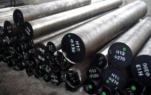 Image Credit: Taybro Alloys Stainless Steel
Carbon is the most important component in commercial steel alloy. Increasing carbon content increases hardness and strength and improves hardenability. But carbon also increases brittleness and reduces weldability because of its tendency to form martensite.
While there are steels that have up to 2% carbon content, they are the exception. Most steel contains less than 0.35% carbon. Now, any steel in the 0.35% to 1.86% carbon content range can be hardened using a heat-quench-temper cycle.
Most commercial steels are classified into one of three groups:
1. Plain carbon steels
2. Low-alloy steels
3. High-alloy steels
Image Credit: Taybro Alloys Stainless Steel
Carbon is the most important component in commercial steel alloy. Increasing carbon content increases hardness and strength and improves hardenability. But carbon also increases brittleness and reduces weldability because of its tendency to form martensite.
While there are steels that have up to 2% carbon content, they are the exception. Most steel contains less than 0.35% carbon. Now, any steel in the 0.35% to 1.86% carbon content range can be hardened using a heat-quench-temper cycle.
Most commercial steels are classified into one of three groups:
1. Plain carbon steels
2. Low-alloy steels
3. High-alloy steels