PROBLEMS IN BOILERS

Boiler-Maintenance-Repair94926492aff64df7962dc137ded70501

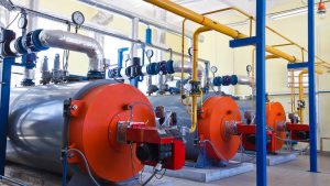
Image Credit:www.globalspec.com


Some common boiler problems are described below:

Fires

Cleanliness of the heat recovery surfaces after the boiler can often be judged by observing the gas pressure differential above and below. Any significant rise in this value should be attended to. Whilst good combustion conditions will minimise the risk, deposits allowed to accumulate in this area are a fire risk and, should fire take hold undetected, it can prove impossible to control and can wreck the heat exchanger, or even the whole boiler. There is plenty of evidence of soot fires leading on to hydrogen fires.


Soot Fires

The ignition of an accumulation of soot, rich in carbon, caused by poor combustion either in ort or when operating at low power for prolonged periods, can when supplied with the necessary oxygen be the source of a fire sufficiently intense to melt and burn steel. Air heaters, with their thin steel plates or air tubes and an abundance of oxygen, can, unless kept clean, be very susceptible to this kind of damage.

Hydrogen Fires

Instances have occurred in which the tubes of watertube boilers, superheaters, economisers and exhaust gas heat exchangers have, as a result of an intense fire, literally melted and run away in streams. Sometimes in the case of vertical tubes, they have melted and flowed back into their headers to solidify. According to the engineers who investigated these cases, the fires were subsequent to the overheating of tubes which were short of water or steam.

Reasons of ‘hydrogen’ fire in a watertube boiler or exhaust gas heat exchanger:

In the watertube boiler the importance of always ensuring an adequate steam circulation through superheaters has already been mentioned, and cannot be overstressed. Additionally, the firing rate, actual location of the superheater in the boiler, the inner and outer surface cleanliness and condition of the superheater tubes, and possible maladjustment of the burner equipment causing ‘flaming through’ screen tubes, can all influence the likelihood of severe overheating of these tubes.

When overheating of a superheater due to insufficient steam circulation is very severe, the tube material may ignite at about 700°C and, burning in the steam, produce free hydrogen. The iron will continue burning independently of any supply of oxygen from the air, and the hydrogen produced by the reaction will burn on coming into contact with air. This means that once such a fire has started there are likely to be two fires burning simultaneously, one, iron burning in steam and the other, hydrogen burning in air, the combined fire being self supporting and probably lasting until the supply of steam is exhausted.

The conditions necessary for the initiation of a hydrogen fire fortunately rare are generally accepted to be as follows:

1. Tube metal temperatures of over 705°C.
2. Tubes with some steam content (usually quiescent or of poor circulation).
3. The presence of a catalyst in the form of a carbon ash.

The extreme importance of adequate steam circulation was vividly demonstrated in one case where one of the two D type main boilers of a VLCC burnt out. In this incident, subsequent to a tube burst and reduction of steam pressure in one boiler, the NR stop valve shut and, before low water level shut off the fuel, a hydrogen fire started in its steam starved superheater. This white hot fire spread throughout the boiler melting and burning most of the tubes, and also initiated soot fire in the air heater. Water wall and screen tube headers were subsequently found to be blocked solid with plugs of steel which had formed when the molten boiler tubes and run back into their holes.

In the foregoing incidents with water tube boilers the source of heat responsible for the overheating has been the boiler burners. Such fires do, however, occur in finned tube exhaust gas heat exchangers and boiler economisers, where the source of heat is flue gas with a temperature much too perchance during a soot fire; the unit concerned is not being circulated, the intense heat of the soot fire, rich in carbon, may initiate a hydrogen fire and that this, as in the case of boiler superheater fires, once started, is self-supporting until al steam is exhausted.

It is important, therefore, that boiler economisers and exhaust gas heat exchangers are kept clean on the gas side to prevent soot fires, and that if defective are either bypassed on the gas side, or if not bypassed have their defective sections properly blanked off, drained and vented.

Sometimes, due to tube failure in an economiser if the individual tube cannot be isolated, or if the failures are of a multiple nature, it becomes necessary to make an emergency bypass of the economiser on the water side. Ordinarily, the gas temperature in this zone will not be sufficiently high to cause any distress to the metal parts, but there will be a fire risk due to the overheating of any deposits on the tubes. Sootblowers should therefore be operated prior to operation with the economiser bypassed, a suitable reduced firing rate should be established and the gas temperature into and out of the bypassed unit monitored, the plant being shut down at the first sign of untoward readings. Such events are also known to have occurred in diesel exhaust gas boilers and, apart from keeping them clean, a sensible precaution with this equipment is to leave the circulating pump running, after the engine is shut down, to cool down the unit and to ensure that air is not admitted until cooler conditions prevail. The only cure is prevention.

Furnace Explosions

Furnace explosions or on a lesser scale ‘blow backs’ generally occur when volumes of oily vapour and air, present in a furnace in explosive proportions, are ignited, although sudden admission of air to a fuel-rich burner flame may well produce the same result. These explosions should not occur in boilers fitted with automatic sequential controls, as these, apart from controlling the fuel to air ratio also ensure adequate purging before ignition.

Even in the best designed system, however, automatic light-up failures do occur, and it is then, when going over to manual control, often in a hurry that the wrong action is sometimes taken, resulting in an explosion. Failure to obtain ignition at the first attempt must be followed by adequate purging.

Explosions in watertube boilers with their large capacity furnaces can, be a serious occurrence, often involving the loss of lives. These explosions usually occur when steaming conditions are not stabilised, as for instance during a vessel’s fitting-out period when steam is intermittently required for testing auxiliaries. At such times the operation of the boiler is sometimes a divided responsibility, and may well be under manual control without all its safety devices completely installed.

Boiler operation should always be the responsibility of one qualified engineer who full appreciates, from the furnace explosion aspect, the vital necessity of adequate pre-ignition purging, and who is aware of the possibility; especially with membrane walled boilers, of a serious furnace explosion pulling tubes out of drums and disgorging the boiler contents into the engine room.

Laying-up Boilers

During idle periods precautions have to be taken to protect boiler internal surfaces against corrosion. Two methods are in common use dependant on the length of lay-up.
For short periods up to say a maximum of one month, the boiler, superheater desuperheater and economiser, with all valves and cocks shut, are completely filled with hot distilled de-aerated alkaline water – daily checks subsequently being made to ensure that fullness and alkalinity are maintained.

In the second methods, used when longer lay-ups are envisaged, the boiler, superheater, desuperheater and economiser are completely dried out using heating stoves in the drums and hot air through the tubes. When dry valves and cocks are shut tight, all doors replaced (using new joints) and the boiler hermetically sealed – trays of a drying agent such as ‘silica gel’; usually being inserted before sealing up.

In the case of auxiliary boilers which operate under intermittent steaming condition corrosive conditions are likely to occur both internally and externally unless precautions are taken during their off periods.

A method frequently used, always assuming steam is available from another source is to embody simmering coils in their water drums. The use of such coils enables a slight pressure to be maintained in the off duty auxiliary boiler, thus eliminating the risk of air ingress, and the gas side is kept warm and dry.

Tube Failures:

Tube failures can occur at very inopportune moments, renewals are costly and a ship may be delayed; it is of the utmost importance, therefore, when active pitting at present, that its cause is established and obviated. In most cases, having established the cause and satisfied oneself regarding the internal condition of the tubes, it is an advantage to chemically clean the boiler so that any oxide scabs covering pits are removed, prior to re-steaming the boiler under corrected water treatment conditions.

While examining steam drums internally attention should be paid to the condition and fastenings of any fittings not removed for access purposes – internal pipes to desuperheaters, internal feed pipes, low-water pipes, low-water alarms and in particular steam driers.

The problems associated with furnace refractory materials, particularly on vertical walls, have resulted in two water-wall arrangements without exposed refractory. These are known as ‘tangent tube’ and ‘monowall’ or ‘membrane wall’.

Fig 2.
Tangential and monowall arrangement
(Source: Seamanship International PC CD-ROM Engineering Knowledge)

In the tangent tube arrangement closely pitched tubes are backed by refractory, insulation and the boiler casing. In the monowall or membrane wall arrangement the tubes have a steel strip welded between them to form a completely gas-tight enclosure. Only a layer of insulation and cladding is required on the outside of this construction.

The monowall construction eliminates the problems of refractory and expanded joints. However, in the event of tube failure, a welded repair must be carried out. Alternatively the tube can be plugged at either end, but refractory materials must be placed over the failed tube to protect the insulation behind it. With tangent tube construction a failed tube can be plugged and the boiler operated normally without further attention.

Sometimes it is difficult to find the failed tube, in an exhaust gas boiler with closely fitted finned tubes for example, a method, which has found success, is ultrasonic detection.
Equipment required is a microphone pickup, connected to an oscilloscope.
• Pressurise the tube stack and headers with air.
• Enter the gas space with the microphone pick up.
• Go round the tube stack with the microphone.
• The maximum air hiss will give the maximum deflection on the oscilloscope.
• The leaking tube will be in that area.
Temporary Repairs To Membrane Or Monowalls At Sea (Ships’ Personnel)
The method of tube repair used in an emergency at sea would depend principally on whether a competent welder and machine are available. If not, the suitable plugs or expandable blind nipples for each of the failed tubes, should be available and also a supply of protective refractory to prevent subsequent burning through of the casing in way of the blanked-off tube.

(a) Welded repairs:

Welded repairs are usually of a patch nature and have the advantage that as the tube remains in use it is not necessary to protect it with refractory. A butt welded patch is preferable, but as this, and also any internally fitted patch, are liable, in the hands of an inexperienced welder, to result in weld splatter entering the tube bore, it is safer for a quick temporary repair to rely on an external fillet welded patch. For repairs of this nature the defective part of the failed tube is cut back to sound material and then a patch piece, preferably cut from a tube having bore equal to the outside diameter of the failed tube, is filet welded over the removed section of the failed tube – the overlap being kept small to prevent subsequent overheating when in service. Subject to a satisfactory hydraulic test on completion such a repair should allow the vessel to reach a port where permanent repairs can be effected (see below).

12
Fig 3.
Permanent welded repair
(Source: Seamanship International PC CD-ROM Engineering Knowledge)

(b) Mechanical repairs:

If a welded repair is impracticable the tube may be plugged at both ends providing the tube is subsequently protected by refractory to prevent local burning of tubes and possible the boiler casing.

Various mechanical plugging methods have been devised by the boiler designers, but lack of internal access and the high temperatures appertaining at shut down can make this an extremely unpleasant and/or lengthy operation. Two methods are described below:

123
Fig 4.
Permanent Mechanical repair
(Source: Seamanship International PC CD-ROM Engineering Knowledge)

Method 1. Windows are cut in the tube about 62mm from its extremities through which wires with taper plugs attached can be pulled the taper plugs having been inserted into the headers via the inspection doors. The plugs are pulled into position through pieces inserted across the windows, and are then pulled up solids by nuts.

After both ends of the tube have been plugged in this manner the whole length of the defective tube and the boiler casing behind it are shielded from the furnace heat during subsequent steaming by a thick shield of plastic refractory.

Method 2. Again windows are cut at each end of the tube through which blind nipples are inserted and subsequently expanded.

It will be appreciated that in this method boiler pressure tends to blow the plugs out whereas in Method 1 boiler pressure tightens the plugs in the hole. It is important to ensure therefore that with this method the expander rollers project down the bore of the nipple beyond the header or drum thickness so that an internal anti blow-out ‘collar’ is formed on the nipple during expanding; as a double precaution special ‘stepped’ roller can be used to form this collar.

As in Method 1, the whole length of the failed tube has subsequently to be shielded from the furnace heat.

Repairs To Membrane Or Monowalls In Port
The type of repair whether accepted as permanent or semi-permanent will depend largely on the availability of welders skilled in this type of work.
Inserting a new section
The obvious and most straightforward permanent repair consists of cutting out the defective length of tube along with part of its adjoining membranes and butt welding in a new section. This repair entails the services of skilled welders, the removal of casing and refractory in way of the repair, and accurate weld preparation.

1234
Fig 5.
Insert repair
(Source: Seamanship International PC CD-ROM Engineering Knowledge)

It is important to note that unless welders skilled in the type of repair are available, the surveyor should insist that the welders being employed do a preliminary procedure test to his satisfaction.

Fish mouth tube replacement method
23
Fig 6.
Fish mount tube replacement method
(Source: Seamanship International PC CD-ROM Engineering Knowledge)

This method, when carefully executed, is also acceptable as a permanent repair and has the advantage that as all welding is done from the furnace it is not necessary to disturb the boiler casing and refractory.

The defective part of the tube along with part of its adjoining membranes are burnt out, as in the previous method. The replacement piece of tube is prepared with its top and bottom ends cut off at 45° to give access when the replacement is in position for welding, from the furnace, the rear part of the two circumferential butt welds.

When these rear parts of the circumferential welds have been satisfactory completed, wedge-shaped pieces of tube are welded into the two windows, and the circumferential butt weld then complete working from the outside. The membranes are subsequently closed by welding as in the previous method.

The configuration of the wedge pieces can be varied to suit tube diameter and access required and, if necessary, backing rings may be used.

The loose ring method
34
Fig 7.
Loose ring method
(Source: Seamanship International PC CD-ROM Engineering Knowledge)

In ports where it is doubtful whether the experience of the welders justifies their employment on the previous two methods of repair, it is possible by this ‘loose ring’ method, to make an acceptable repair of a semi-permanent nature using down hand welding.

In this method access has to be made all around the tube and loose rings with cupped upper surfaces are slid into position in way of the butts to be welded, so that an inexperienced welder has a better chance of making a butt cum fillet joint. In all other aspects the repair is as in the previous two cases.

In view of the extra metal thickness in way of the rings and possible build up of weld metal this repair could subsequently be the subject of overheating in service, and on that account the repair should only be regarded as semi-permanent.

Testing

On completion of any of the foregoing repairs whether temporary or permanent, the boiler should be subjected to a working pressure hydraulic test. In the case of the repairs effected in port the welds should be crack detected and, if possible, X-ray detection equipment should be used.

REFERENCE

1. Leslie Jackson & Thomas D Morton Reed’s General engineering knowledge for marine engineers (2002) Thomas Reed, pgs 89 – 136
2. Leslie Jackson & Thomas D Morton, Reed’s Motor engineering knowledge for marine engineers (2002) Thomas Reed, pgs 178 – 198
3. Seamanship International PC CD-ROM (2004) Engineering knowledge
4. www.marineengineering.co.uk
5. www.marinediesels.info

FUEL INJECTOR OF DIESEL ENGINES

Image Credit: www.riceweightloss.com

Older loop scavenged engines may have a single injector mounted centrally in the cylinder head. Because the exhaust valve is in the centre of the cylinder head on modern uniflow scavenged engines the fuel valves (2 or 3) are arranged around the periphery of the head.
The pressure at which the injector operates can be adjusted by adjusting the loading on the spring. The pressure at which the injectors operate vary depending on the engine, but can be as high as 540bar.

FUEL INJECTOR


OPERATION

– Fuel injectors achieve this by making use of a spring loaded needle valve.
– The fuel under pressure from the fuel pump is fed down the injector body to a chamber in the nozzle just above where the needle valve is held hard against its seat by a strong spring.
– As the fuel pump plunger rises in the barrel, pressure builds up in the chamber, acting on the underside of the needle as shown. When this force overcomes the downward force exerted by the spring, the needle valve starts to open.
– The fuel now acts on the seating area of the valve, and increases the lift.
– As this happens fuel flows into the space under the needle and is forced through the small holes in the nozzle where it emerges as an “atomised spray”.
injector_animation (1)
Image Credit: www.marinediesels.co.uk

At the end of delivery, the pressure drops sharply and the spring closes the needle valve smartly.

ATOMIZATION
Fuel Injector
It is the break-up of the fuel change into a very small particles when it is injected into the cylinder
Proper atomization facilitates the starting of the burning and ensures that each minute particle of fuel is surrounded by oxygen particles which it can combine
download
Image Credit: www.marineinsight.com

PENETRATION

It refers to the distance that the fuel particles travel or penetrate into combustion chamber

TURBULENCE or SWIRL

– It refers to the aim movement pattern within the combustion chamber at the end of compression.
The spray pattern of the fuel is cone-shaped.
123
– These occurs when there is an excess velocity of fuel spray during injection, causing contact with metallic engine parts and one result is flame burning

INJECTOR NOZZLE:

The body of a fuel injector valve is normally flanged at the upper end and the lower end is threaded to accommodate the nozzle body and nozzle cap nut
The nozzle body contains four holes. One is for the fuel inlet and another for the fuel priming valve, these two holes are connected through a common space within the fuel nozzle or by annular space
images (1)
Image Credit: DieselNet

The valve needle which has been lapped into a very accurately machine guide into the nozzle body, is held on the conical seat immediately above the atomization holes
Slightly clearance between needle and nozzle body to allow for temperature changes when working with heated fuel.

COOLING OF FUEL INJECTION VALVE:

Some injectors have internal cooling passages in them extending into the nozzle through which cooling water is circulated. This is to prevent overheating and burning of the nozzle tip.
Injectors on modern 2 stroke crosshead engines do not have internal water cooling passages. They are cooled by a combination of the intensive bore cooling in the cylinder head being close to the valve pockets and by the fuel which is recirculated through the injector when the follower is on the base of the cam or when the engine is stopped.

As well as cooling the injector, recirculating the fuel when the engine is stopped keeps the fuel at the correct viscosity for injection by preventing it from cooling down.
The animation opposite shows the principle on which one system operates.
Fuel injectors must be kept in good condition to maintain optimum efficiency, and to prevent conditions arising which could lead to damage within the cylinder. Injectors should be changed in line with manufacturers recommendations, overhauled and tested. Springs can weaken with repeated operation leading to the injector opening at a lower pressure than designed. The needle valve and seat can wear which together with worn nozzle holes will lead to incorrect atomisation and dribbling

FAULTS OF FUEL INJECTORS:

1. Over heating OR under cooling:
If cooling of the injector is reduced, either by fuel valve cooling system or poor heat transfer to the cylinder head, then the working temperature of the injector will rise. This can cause:-
– Softening of the needle and seat which increases the possibility of nozzle leakage and/or,
– Fuel to expand/boil out of the fuel sac, leading to carbon trumpet formation, and increased levels of HC and smoke in the exhaust gases.

2. Over cooling:
More common on older vessels with separate fuel valve water cooling systems. When the injector is over cooled, the tip of the injector falls below the condensation temperature and acid corrosion due to the sulphur in the fuel oil occurs. This can severely corrode the injector tip, causing the spray pattern to be affected.

3. leakage from Nozzle:
This fault will produce carbon trumpets as the dribble of fuel burns close to the tip and the carbon deposits remain. The formation of the trumpets will have a progressive affect by influencing the spray pattern of the fuel, and this can be detected in the increased exhaust gas temps and smoke levels.
Nozzle leakage can sometimes be identified by a seat defect(the seat is no longer narrow in appearance, and is caused by):-
– Insufficient cooling,
– Dirt within the fuel damaging/abrading the seating area,
– Excessive needle valve hammering, due to excessive time in service, excessive needle lift or spring force.

4. Weak spring:
This will cause the injector to open and close at a lower pressure. Thus the size of the fuel droplets will increase during these injection periods.
Increased droplet size at the start of combustion will decrease the maximum cylinder pressure (late combustion), whilst increased droplet size at the end of combustion will increase the exhaust temperature and smoke (afterburning).
Causes of a weak spring are usually metal fatigue, due to an excessive number of operations.

5. Slack needle:
Slight leakage between the needle valve and its body is required to provide lubrication of the moving parts. However excess leakage due to a slack needle will allow a greater quantity, and larger size of fuel particle to pass between the valve and body.
The quantity of leakage should not influence injector performance unless excessive, but dirt particles between the needle and body can increase friction and make the needle action sluggish.
The cause of a slack needle is usually poor filtration of the fuel causing wear between needle and body.

6. Poor atomisation:
This will increase the size of the fuel droplets, which will increase the time required for combustion. Thus engine noise, exhaust smoke, exhaust temperatures, etc will increase. Poor atomisation can be caused by low injection pressure (fuel pump wear), high fuel viscosity and nozzle hole obstruction such as carbon trumpets.

7. Poor penetration
This will reduce the mixing which occurs between the fuel and air, and will increase the over-rich areas in the centre area of the cylinder. Thus only following combustion in the centre area will the expanding gases move the fuel charge into the air rich outer ring of the cylinder where the greatest mass of air is present.
This will increase the time required for combustion as the fuel/air mixture is not correct in many areas, and hence afterburning, exhaust temps, and smoke will increase.
Causes of poor penetration is reduced injection pressure, and nozzle hole blockage such as trumpets or sac deposits.

8. Over penetration
This will occur when the air density within the cylinder is reduced, or with over-size holes. The liquid stream travels too far into the cylinder, so that a high level of liquid impingement on the liner wall takes place. This will remove the liner lubrication, and once burning will greatly increase the liner wall temperature, and its thermal stress.
If this over penetration is caused by prolonged low power operations, then “slow speed” nozzles should be fitted.

Slow steaming nozzles can be used when regular and prolonged engine operation is required between 20-50% power.
The nozzle hole diameter is reduced to
i. Reduce the penetration that will occur into the less dense cylinder air
ii. Keep the atomisation level and injection pressure sufficient, as mass flow rate is reduced.

If the engine is operated for long period on low levels of power/speed with `normal’ size injector nozzles, then the atomisation will reduce, thus engine noise, mechanical loading, exhaust smoke, exhaust temps, and fuel consumption will increase.

EFFECT OF FAULTY FUEL INJECTORS:

1. Greatly enlarged holes cause overheating, perhaps burning of piston upper surface, also cause carbon deposits in the piston cooling space, if oil cooled. It may also cause increased cylinder and piston ring wear

2. If the holes are chocked, the fuel sprays will be effected to the extent that imperfect combustion will result. This in turn may reduce the power output quite considerably and bring about all the mechanical troubles usually associated with after burning.
3. If the injectors leaky or spring is damaged, burning of piston upper surface, also cause carbon deposits in the piston cooling space, if oil cooled. It may also cause increased cylinder and piston ring wear and can lead to scavenge fire.

INDICATION OF FAULTS:

1. Early injection is usually evidenced by knocking in the cylinder. On the power diagram the maximum pressure will be considerably in excess. Exhaust temperature will be low.

2. Leaky valve can be detected through indicator diagram, which show reduced combustion pressure. This will be some reduction in power output, increasing in exhaust temperature about 10oC and smoky gases. Chocking of atomizer and exhaust ports. Surging in turbo-blower are also some of the indication

3. After burning will cause higher exhaust temperature and pressure. The maximum height of both the power and draw diagram would be reduced. Other indications are smoky exhaust, possible fires in uptake, fouling of exhaust system, surging of turbo-blower

4. Choked fuel injectors – combustion efficiency of an engine depends on fuel atomization, shape and direction of the fuel sprays. So the holes should be clear and clean. First outward indication of accumulation of carbon deposits will be increase in the exhaust temperature due to fuel not mixing properly with the air, consequently not burning completely in the allocated time. Power output is reduced and the exhaust is smoky.

MAINTENANCE

  • Fuel injectors must be kept in good condition to maintain optimum efficiency, and to prevent conditions arising which could lead to damage within the cylinder.
  • Injectors should be changed in line with manufacturers recommendations, overhauled and tested.
  • Springs can weaken with repeated operation leading to the injector opening at a lower pressure than designed.
  • The needle valve and seat can wear which together with worn nozzle holes will lead to incorrect atomization and dribbling.
  • Proper cooling should be made during operation. Cooling passages to be cleaned during overhaul.
  • Proper grade of fuel oil should be used and it should be used after proper purification to prevent atomized holes become enlarged, conical and oval due to abrasive materials.
  • The valve body and valve needle should always be considered as a unit, not as two separate pieces and they should be renewed together.
  • The holes should be cleaned and cleared properly without damaging by blown with compressed air.
  • The valve needle must be perfectly fluid tight when in the closed position and must open and close smartly.
  • The cam operating the fuel valves or the fuel pump, as the case may be, should effect opening and closing in the shortest time practicable.


References:

1. www.marineengineering.co.uk
2. The Running and Maintenance of Marine Machinery – Cowley
3. Reeds Marine Engineering Series, Vol. 12 – Motor Engineering Knowledge for Marine Engineers
4. Lamb’s Question and Answers on Marine Diesel Engines – S. Christensen
5. Principles and Practice of Marine Diesel Engines – Sanyal

LATEST DEVELOPMENT ON ENERGY-EFFICIENCY IN INTERNATIONAL SHIPPING BY IMO (MEPC 68TH SESSION)

(Energy-efficiency and air pollution implementation at IMO environment meeting, Marine Environment Protection Committee (MEPC), 68th session.11-15 May 2015)

Seagull clean ocean_LA_2
Further development of energy-efficiency guidelines for ships

The MEPC continued its work on further developing guidelines to assist in the implementation of the mandatory energy-efficiency regulations for international shipping and:

• adopted amendments to update the 2014 Guidelines on survey and certification of the Energy Efficiency Design Index (EEDI) and endorsed their application from 1 September 2015, at the same time encouraging earlier application;

• adopted amendments to the 2013 Interim Guidelines for determining minimum propulsion power to maintain the manoeuvrability of ships in adverse conditions, for the level-1 minimum power lines assessment for bulk carriers and tankers, and agreed on a phase-in period of six months for the application of the amendments; and
• adopted amendments to update the 2014 Guidelines on the method of calculation of the attained EEDI for new ships.

EEDI review work to continue

The Committee considered a progress report from the correspondence group established to review the status of technological developments relevant to implementing phase 2 of the EEDI regulations, as required under regulation 21.6 of MARPOL Annex VI and re-established the correspondence group to further the work and submit an interim report to MEPC 69.

Text agreed for further development of a data collection system to analyse the energy efficiency of ships

The MEPC agreed text for its further development to be the full language for the data collection system for fuel consumption of ships, which can be readily used for voluntary or mandatory application of the system. In this regard, the Committee noted that a purpose of the data collection system was to analyse energy efficiency and for this analysis to be effective some transport work data needs to be included, but at this stage the appropriate parameters have not been identified.

The proposed text refers to ships of 5,000 GT and above collecting data, to include the ship identification number, technical characteristics, total annual fuel consumption by fuel type and in metric tons and transport work and/or proxy data yet to be defined. The methodology for collecting the data would be outlined in the ship specific Ship Energy Efficiency Management Plan (SEEMP).

Data would be aggregated into an annual figure and reported by the shipowner/operator to the Administration (flag State) which would submit the data to IMO for inclusion in a database. Access to the database would be restricted to Member States only and data provided to Member States would be anonymized to the extent that the identification of a specific ship would not be possible.

The MEPC agreed to recommend to the IMO Council the holding of an intersessional working group to: further consider transport work and/or proxies for inclusion in the data collection system; further consider the issue of confidentiality; consider the development of guidelines identified in the text; and to submit a report to MEPC 69.

GHG reduction target for international shipping considered

The MEPC considered a submission from the Marshall Islands, calling for a quantifiable reduction target for greenhouse gas emissions from international shipping.

During the discussion, the Member States that spoke acknowledged and recognised the importance of the issues raised by the Marshall Islands and also recognised that, despite the measures already taken by the Organization regarding the reduction of emissions from ships, more could be done.

However, whilst expressing gratitude to the Marshall Islands for the submission, the Committee took the view that the priority at this stage should be to continue its current work, in particular, to focus on further reduction of emissions from ships through the finalization of a data collection system. The Marshall Islands proposal could then be further addressed at an appropriate future session of the Committee. ​The need to consider the proposal further was recognised and the Committee also looked forward to a successful UN climate change conference (UNFCCC COP 21 meeting) in Paris later this year.

Revised air pollution guidance and requirements agreed

The MEPC considered a number of amendments and revisions to existing guidance and requirements related to air pollution measures and in particular:

  • • adopted amendments to the 2009 Guidelines for exhaust gas cleaning systems (resolution MEPC.184(59)). The amendments relate to certain aspects of emission testing, regarding measurements of carbon dioxide (CO2) and sulphur dioxide (SO2), clarification of the washwater discharge pH limit testing criteria and the inclusion of a calculation-based methodology for verification as an alternative to the use of actual measurements;
    • approved, for adoption at MEPC 69, draft amendments to the NOX Technical Code 2008 to facilitate the testing of gas-fuelled engines and dual fuel engines for NOx Tier III strategy;
    • approved, for adoption at MEPC 69, draft amendments to MARPOL Annex VI regarding record requirements for operational compliance with NOX Tier III emission control areas;
    • approved Guidance on the application of regulation 13 of MARPOL Annex VI Tier III requirements to dual fuel and gas-fuelled engines; and
    • adopted amendments to the 2011 Guidelines addressing additional aspects to the NOX Technical Code 2008 with regard to particular requirements related to marine diesel engines fitted with Selective Catalytic Reduction (SCR) Systems (resolution MEPC.198(62)).

The Committee also agreed, for consistency and safety reasons, to proceed with the development of guidelines for the sampling and verification of fuel oil used on board ships.

Fuel oil availability review to be initiated this year

The MEPC agreed terms of reference for the review, required under regulation 14 (Sulphur Oxides (SOx) and Particulate Matter) of MARPOL Annex VI, of the availability of compliant fuel oil to meet the global requirements that the sulphur content of fuel oil used on board ships shall not exceed 0.50% m/m on and after 1 January 2020. The IMO Secretariat was requested to initiate the review by 1 September 2015, with a view to the final report of the fuel oil availability review being submitted to MEPC 70 (autumn 2016) as the appropriate information to inform the decision to be taken by the Parties to MARPOL Annex VI.

A Steering Committee consisting of 13 Member States, one intergovernmental organisation and six international non-governmental organizations was established to oversee the review.

The sulphur content (expressed in terms of % m/m – that is, by weight) of fuel oil used on board ships is required to be a maximum of 3.50% m/m (outside an Emission Control Area (ECA)), falling to 0.50% m/m on and after 1 January 2020. Depending on the outcome of the review, this requirement could be deferred to 1 January 2025. Within ECAs, fuel oil sulphur content must be no more than 0.10% m/m.

Fuel oil quality correspondence group re-established

The MEPC considered the report of the correspondence group established to consider possible quality control measures prior to fuel oil being delivered to a ship. The correspondence group was re-established to: further develop draft guidance on best practice for assuring the quality of fuel oil delivered for use on board ships; further examine the adequacy of the current legal framework in MARPOL Annex VI for assuring the quality of fuel oil for use on board ships; and submit a report to MEPC 69.

Black carbon definition agreed

The MEPC agreed a definition for Black Carbon emissions from international shipping, based on the “Bond et al.” definition which describes Black Carbon as a distinct type of carbonaceous material, formed only in flames during combustion of carbon-based fuel, distinguishable from other forms of carbon and carbon compounds contained in atmospheric aerosol because of its unique physical properties.


For details, please click the below link:
http://www.imo.org/MediaCentre/PressBriefings/Pages/19-MEPC-ends.aspx#.VVvj5_mqqko​​
​​
IMO Briefing: 19, May 18, 2015.
Web site: www.imo.org

WÄRTSILÄ TO DELIVER SCRUBBER SYSTEMS TO CLEAN THE EXHAUST FROM TWO DUTCH RORO CARRIERS

1
Royal Wagenborg, the Dutch ship owner and operator, has ordered Wärtsilä scrubber systems to clean the exhaust emissions from two of its RoRo carriers, the ‘Balticborg’ and ‘Bothniaborg’. These will be Wärtsilä’s first deliveries of its scrubber systems to Royal Wagenborg.


By installing Wärtsilä scrubber systems, the vessels will comply with the regulations covering emissions of sulphur oxides (SOx) while using conventional residual marine fuel (HFO).

The systems chosen for these vessels are Wärtsilä Hybrid Scrubbers, which enable the use of either closed or open loop technology to remove SOx from the exhaust. When operating in open loop mode, exhaust gases enter the system and are sprayed with seawater. The sulphur oxides in the exhaust react with the water to form sulphuric acid. Chemicals are not required since the natural alkalinity of seawater neutralizes the acid. When operating in closed loop mode, the natural alkalinity of seawater is boosted by an alkali. The hybrid approach enables operation in closed loop mode when required, for instance whilst in port and during manoeuvring using NaOH as a buffer. When at sea, the switch can be made to open loop using only seawater.

Wärtsilä Press Release.

WÄRTSILÄ 50DF ENGINE CAPABLES TO OPERATE ON ETHANE GAS

wartsila-50df
The market leading Wärtsilä 50DF marine engine has been successfully tested and certified to run on ethane (LEG) fuel. The extensive and successful testing programme was carried out by Wärtsilä in close collaboration with Evergas, a world renowned owner and operator of seaborne petrochemical and liquid gas transport vessels.


“We are very pleased that the Wärtsilä engines will be capable of utilising ethane boil-off gas as fuel. It increases our operational efficiency and improves flexibility in the bunkering of fuels. All in all it results in a significant reduction in operating costs, while also providing a minimal environmental footprint. It also enables us to offer our customers increased flexibility, which has a monetary value to them,” says Mr Steffen Jacobsen, the CEO of Evergas.

The capability to efficiently burn ethane boil-off gas as engine fuel significantly reduces the need of gas re-liquefaction during the voyage. This means that less power is needed for the cargo handling, thus providing a more efficient and environmentally sound overall system.

This technological breakthrough enables Wärtsilä’s customers to meet the International Maritime Organization’s (IMO) Tier III regulations without need of secondary emissions cleaning while using either LNG or LEG as fuel. The engines have the capability to seamlessly switch between Liquified Natural Gas (LNG), Ethane (LEG), Light Fuel Oil (LFO) or Heavy Fuel Oil (HFO) without the need for any modifications to hardware and with uninterrupted operation, thereby setting a new standard in fuel flexibility.

Wärtsilä press release.

AUDI E-DIESEL- FUEL OF THE FUTURE

audi-fuel
After a commissioning phase of just four months, the research facility in Dresden started producing its first batches of high‑quality diesel fuel a few days ago.
The Dresden energy technology corporation sunfire is Audi’s project partner and the plant operator. It operates according to the power‑to‑liquid (PtL) principle and uses green power to produce a liquid fuel. The only raw materials needed are water and carbon dioxide. The CO2 used is currently supplied by a biogas facility. In addition, initially a portion of the CO2 needed is extracted from the ambient air by means of direct air capturing, a technology of Audi’s Zurich‑based partner Climeworks.

Production of Audi e‑diesel involves various steps: First, water heated up to form steam is broken down into hydrogen and oxygen by means of high-temperature electrolysis. This process, involving a temperature in excess of 800 degrees Celsius, is more efficient than conventional techniques because of heat recovery, for example. Another special feature of high-temperature electrolysis is that it can be used dynamically, to stabilize the grid when production of green power peaks.
In two further steps, the hydrogen reacts with the CO2 in synthesis reactors, again under pressure and at high temperature. The reaction product is a liquid made from long‑chain hydrocarbon compounds, known as blue crude. The efficiency of the overall process – from renewable power to liquid hydrocarbon – is very high at around 70 percent. Similarly to a fossil crude oil, blue crude can be refined to yield the end product Audi e‑diesel. This synthetic fuel is free from sulfur and aromatic hydrocarbons, and its high cetane number means it is readily ignitable. As lab tests conducted at Audi have shown, it is suitable for admixing with fossil diesel or, prospectively, for use as a fuel in its own right.
To demonstrate its suitability for everyday use, Federal Minister of Education and Research Prof. Dr. Johanna Wanka put the first five liters into her official car, an Audi A8 3.0 TDI clean diesel quattro*, this Tuesday. “This synthetic diesel, made using CO2, is a huge success for our sustainability research. If we can make widespread use of CO2 as a raw material, we will make a crucial contribution to climate protection and the efficient use of resources, and put the fundamentals of the “green economy” in place,” declared Wanka.

Audi Press release