Author Archives: Mohammud Hanif Dewan

marpol convention

SUMMARY OF MARPOL AND SOLAS AMENDMENTS ENTERING INTO FORCE FROM 01 JANUARY 2020

MARPOL:

Annex VI 0.50% Sulphur Limit: The limit for sulphur in fuel oil used on board ships to be reduced to 0.50% m/m (mass by mass).

SOLAS:

Amendments to SOLAS regulations III/3 and III/20 to make mandatory the requirements for maintenance, thorough examination, operational testing, overhaul and repair of lifeboats and rescue boats, launching appliances and release gear.

Amendments to SOLAS regulation II-2/13 to extend the requirements for evacuation analysis to all passenger ships, not just RO-RO passenger ships.

Continue reading

marpol convention

IMO SULPHUR REGULATIONS 2020

The 2020 IMO global 0.50 percent fuel Sulphur Technical Note:

In less than a week time, From 1st January 2020, the maximum permissible global Sulphur content of marine fuels is going to be reduced from

3.5 % to 0.5% according to MARPOL Annex VI. Ships operating outside

Emission Control Areas (ECAs) will have three options to achieve compliance:

  1. By the use of exhaust gas abatement technology (‘scrubbers’), or
  2. By burning a fuel with maximum Sulphur content of 0.50%mass, or
  3. By burning LNG. To meet continuing legislation inside ECAs.

Continue reading

BARRIERS FOR ADOPTION OF ENERGY EFFICIENCY OPERATIONAL MEASURES IN SHIPPING INDUSTRY

ABSTRACT:

A greenhouse gas (GHG) study by the International Maritime Organization (IMO) estimates the total carbon dioxide emissions (CO2) by the shipping industry in 2012 was 2.7% of global CO2 emissions. Unless the shipping industry takes some control measures, by 2050 these emissions are expected to increase by up to 250% from their 2012 levels. Although the cost-reducing effects of some measures and new technologies are well established, shipping companies appear reluctant to adopt them.

Continue reading

Ship Engineer.

MAINTENANCE AND IT’S TYPES

What is Maintenance?

The technical meaning of “maintenance” involves functional checks, servicing, repairing or replacing of necessary devices, equipment, machinery and supporting utilities in industrial and residential installations.

Objectives of Maintenance

  • Minimize loss of productive time
  • Minimize repair time & cost
  • Keep productive assets in working condition
  • Minimize accidents
  • Minimize total maintenance cost
  • Improve the quality of products

Continue reading

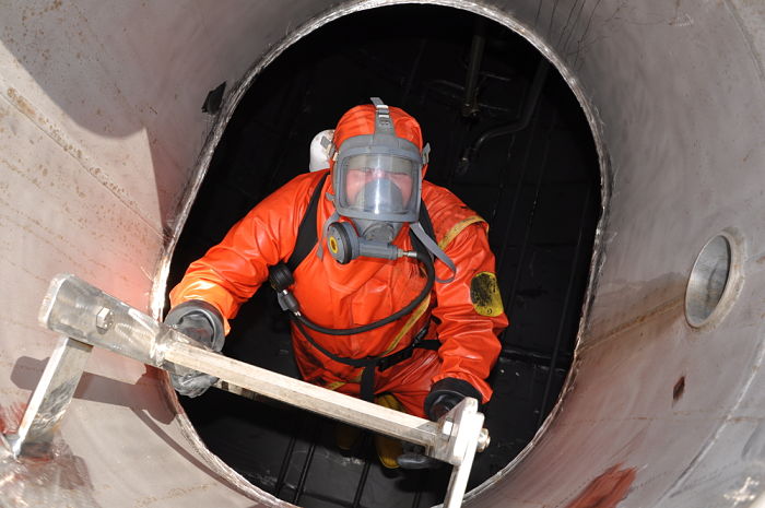
ENCLOSED SPACE DANGERS AND ENTRY PROCEDURE

Author: Md Taifur Rahman

Dangers of entering an enclosed space:

  1. Toxic atmosphere

A toxic atmosphere may cause various acute effects including impairment of judgment, unconsciousness and death.

  1. Oxygen deficiency

     Can be lacking for:

  • Displace of air by another gas
  • Various biological processes or chemical reaction
  • Absorption of air

3. Flammable or explosive atmosphere

A flammable atmosphere present a risk of fire or explosion. Such atmosphere can arise from the presence of flammable liquid or gas or suspended combustible dust in air inside the enclosed space.

  1. The flowing dangers may present too like:
  • Oxygen enrichment
  • Flowing liquid or free flowing solids
  • Excessive heat.

Implementation of “Permit-to-enter” system for entry into enclosed spaces:

  • Before entering an enclosed space must have a valid permit
  • Entry into enclosed space check list must be followed according the SMM manual
  • The space must be segregated by blanking off or isolation
  • The space must be properly ventilated.
  • Proper and practicable atmosphere testing must be carried out.
  • Frequent atmosphere check during work must be carried out.
  • Must have a continuous Ventilation during work
  • Rescue team and related equipment’s including SCBA to be kept ready
  • Must have a designated person at the entrance of enclosed space to alert for help.
  • Designated person should ensure the entry persons wearing proper PPE with SCBA
  • The duty officer in Bridge/ CCR/ECR should be known about the entry
  • A reliable means of communication should be agreed and tested.
  • In case of failure of ventilation system the person should leave the place immediately.
  • There has to be a system to record entry and leaving enclosed space
  • A reporting time interval from enclosed space should be agreed.

After completion of work designated person should ensure entry persons and related equipment’s are safely withdrawn.

crankcase explosion

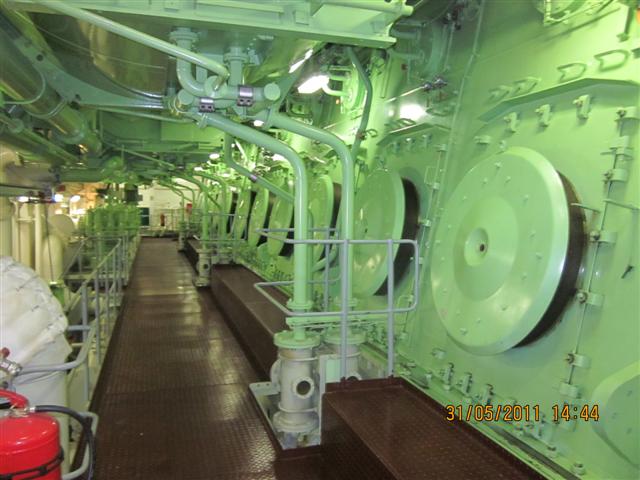
CRANKCASE INSPECTION

Author: Md Taifur Rahman

Preparation:

  • Toolbox meeting carried out.
  • Carry out a proper risk assessment and work permit taken
  • Enclosed is space entry permit to be taken and enclosed space entry procedure to be followed
  • Inform bridge and put warning notice at ECR
  • Block the starting mechanism and stop the L.O pump
  • Open indicator cocks and engage turning gear
  • Propeller clearance taken
  • Turning gear must be operated only in remote mode
  • All personnel involved should not have any object in their pocket
  • Instrument/tools to be used should be checked and counted

Continue reading

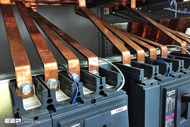
ISOLATED AND EARTHED NEUTRAL SYSTEM

Author: Usman Karneh

The function of an electrical system is to safely convey the power from the point of generation (source) to where it is required the various loads or equipment connected to it. The electrical source, like the load may either be a single phase (2-wire) or three phase (3 to 4- wire) system
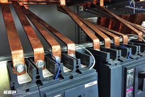

An electrical system can take any of two forms:
Neutral Insulated system, or
Neutral Earthed system.
For single phase neutral insulated system, the neutral of the source is insulated. In other words, the neutral is not connected to the earth. While for the neutral earthed system, the neutral of the source is connected to the earth.
For three phase star neutral insulated system, the common point of the source is not connected to earth. Hence there are only 3 phase wires R,Y,B emerging from the source. In neutral earthed system, the star point is earthed to ground. So 4 wires emanate from source (3 phase and 1 neutral).

Three (3) types of fault may occur in an electrical system:
Open circuit fault: is the result of a break in the conductor so that no current flow through the load.
Short circuit fault: is due to break in insulation and two conductors (line and neutral) are directly touching each other resulting into a short path to current flow and allowing a very large current to bypass the load.
Earth Fault: This is also due to insulation breakdown which somehow allow the conductor to come into direct contact with the metal enclosure or body frame of the equipment.
A single earth fault occurring in the line of an earthed neutral system, would be equivalent to a short circuit fault since this will creates a closed path for the earth current to flow through to the ground as a result of minimal resistance, this earth current may increase to a very large extent. If the earth current increases beyond the current rating of the generator, the entire system may collapse causing irreparable damage. To limit this earth current, a Neutral Earthing Resistor is connected to the earthed neutral of the source. This resistor is of sufficient ohmic value to limit the earth current within rating of the generator. However, the magnitude of earth current is sufficiently large to operate the tripping mechanism of the faulted equipment immediately isolating it from supply and rendering it safe.
A single earth fault in a neutral insulated system, would not cause any earth current to flow. This is because a single earth fault current does not provide a complete circuit for earth current to flow. So no protective trip will operate and system will continue to function normally.
However, if a second earth fault occurs on another line in the insulated system, the two earth faults together will be equivalent to a short circuit and the resulting earth fault current will operate the available protection devices and cause disconnection of services.
For system where the priority requirement is to maintain continuity of the electrical supply to essential equipment in event of a single earth fault occurring the isolated neutral (neutral insulated) system is used. For system where the priority requirement is the immediate isolation of earth-faulted equipment is automatically achieved by a neutral earthed system.

To understand this better, a case study is used; If the earth fault occurs in an essential system like that of steering gear of a ship, then in case of: Insulated neutral system, no earth fault current will flow and the steering gear will continue to operate until there is a second earth fault in any equipment present onboard. Hence, with a single earth fault, the essential service will continue to operate.
If the system would have been an earthed neutral, then a single earth fault would have caused heavy earth current to flow and operate the tripping mechanism causing shutting down of steering gear. This will seriously compromise the safety of the ship navigation. Hence, it is well understood that onboard a ship, a neutral insulated system is to be used while, in an industry or on shore installations neutral earthed system is used.
Shipboard main LV systems at 440 V are normally provided with neutral insulated system. On the other hand HV system (1000 V to 3.3 KV) are usually provided with neutral earthed system via a neutral earthing resistor.
In a HV system, certain essential loads can be supplied by a transformer with it’s secondary insulated to ensure no earth fault current flows in the equipment in order to maintains the continuity of service.

Shipping regulations require that the hazardous areas of tanker such as the cargo area, pump room should have a neutral insulated system to prevent any stray earth current from flowing in the hull and causing explosion hazard.
However an exception is included in case if tanker has a 3.3 KV system, the earthed system is permitted provided that the earthed system does not extend forward of engine room bulkhead and into the hazardous area.

Both the Insulated neutral and Earthed neutral system have got their own advantages and disadvantages. Where it is easier in the earthed neutral system to detect any earth faults in system, it is easier in isolated neutral system to maintain the continuity of service.

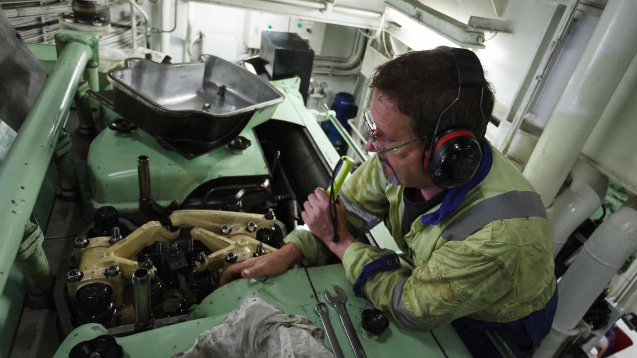
ACCIDENTAL AGROUNDING: CHIEF ENGINEER’S RESPONSIBILITY

Once a vessel has grounded there are a number of considerations that need to be addressed:

  • Has the hull of the vessel been broached during grounding. Sounding all the various tanks that are situated behind the outer hull can check this. If the hull has been broached, then the vessel should not be refloated unless it is determined that sufficient buoyancy and stability remains once the vessel is floating freely.
  • Has the hull of the vessel been deformed in any way. This could lead to increased bearing loads on the main engine and/or main transmission shafting
  • Has the propeller or rudder become fouled or damaged. Ensuring both units are free to rotate without any excess loads could check this.
  • Is the vessel discharging any oil. A check on the tank levels may assist in locating possible damage, but any external pollution should be controlled as soon as practical.
  • Are the sea suction intakes blocked/covered by the seabed. Any reduction in the seawater pressure could require that the sea suctions be changed over.

 Soundings around the vessel should take place to determine where the vessel has grounded, and the type of seabed on which the vessel is laid.

Once the vessel has been grounded there should be an estimate of when the vessel may be re-floated. This could depend on the local tides, vessel loading condition, and vessel ballast condition. If the vessel were fully loaded, then discharge of the cargo may take a number of days, then it may be prudent to reduce the services supplied by the engine room. This will reduce the fuel consumption whilst aground. The limit of services may be dictated by any possible damage to the vessel’s hull.

One area of concern may be that the if the engine were normally operating on residual fuel, then to keep the fuel injection system warm this has to be circulated at all times. Should a fuel injector be leaking, then this could cause a build-up of fuel on top of the piston, which will cause excessive pressure rises when the engine has started. Thus the main engine should be changed over to diesel oil. This change over must avoid high rates of temperature changes, and once fully flushed the fuel oil system can be shutdown until the main engine is required again.


Once the vessel has been re-floated, then the following inspections should take place:

  • An in-water survey should be carried out with the agreement of the Classification Society. This will require that the vessel be in clear water, so that divers can examine the underwater portion of the hull. They will examine all hull plating, looking for dents, holes, etc.
  • A function test of the rudder and transmission shafting
  • A full set of crankshaft deflections should be taken. The readings obtained should be compared with previous readings, and also be within the engine manufacturer’s recommendations for that engine. Whilst measuring the deflections, bridge gauge readings may also be taken to ensure that the crankshaft is sitting firmly on the lower bearing half.
  • Even though the divers are examining the external hull shell plate, it may also be prudent to examine the cofferdam in way of the main engine seating, to ensure that the full strength of this important seating area is intact before engine power is resumed.

CHECKING PERFORMANCE OF MAIN ENGINE

In order to monitor the engine performance, we would need to measure the power output and fuel consumption of the engine. This will allow the performance of the engine to be measured against previous and even test bed readings.

The staff would be instructed to the followings:

  • Measure the power of the each cylinder by electronic pressure measurement. If the engine was driving an electrical load, then the electrical output power could be used. This will allow the total engine power to be calculated, and also for any power imbalance to be detected. This power measurement would be taken every month.
  • Measure the fuel consumption of the engine every day over a 8 and 24 hour period. This consumption would be measured in tonne/hour, and thermal and density conversions from a volumetric flow rate at the meter would be required.
  • Calculate the specific fuel consumption of the engine in terms of g/kWh, so that fuel consumption at various engine conditions could be compared.

Engine room staff would be instructed to the followings:

  • Closely monitor the pressure differential across the lube oil filters each day, and to report any increase in this pressure, or the frequency of automatic filter blowdown.
  • Take a representative sample from the lube oil inlet to the engine every week.
  • This sample would be tested on board for
  • Water content
  • Change in viscosity
  • BN reserve
  • In addition every month a representative sample would be taken and sent for shore analysis so that a wider range of variables could be analysed.

The general condition of the engine could be monitored by measuring the various parameters taken by the data logger or manual log readings.

The staff would be instructed to the followings:

  • Take a full set of readings twice a day on all the major parameters of the engine, such as
  • Exhaust gas temperatures
  • Lube oil pressure and temperature
  • Fresh water cooling pressure and temperature
  • Scavenge air pressure and temperature
  • T/C rev/min
  • Exhaust gas smoke levels
  • These readings would form the basis of the datum readings for that engine, and any major changes to the measurements should be reported to the Chief Engineers without delay.
  • In addition, should electronic power measurement not be available on-board, then peak pressure readings of each cylinder would be taken monthly to ensure even loading of the cylinders