Author Archives: Mohammud Hanif Dewan

FUEL INJECTOR OF DIESEL ENGINES

Image Credit: www.riceweightloss.com

Older loop scavenged engines may have a single injector mounted centrally in the cylinder head. Because the exhaust valve is in the centre of the cylinder head on modern uniflow scavenged engines the fuel valves (2 or 3) are arranged around the periphery of the head.
The pressure at which the injector operates can be adjusted by adjusting the loading on the spring. The pressure at which the injectors operate vary depending on the engine, but can be as high as 540bar.

FUEL INJECTOR


OPERATION

– Fuel injectors achieve this by making use of a spring loaded needle valve.
– The fuel under pressure from the fuel pump is fed down the injector body to a chamber in the nozzle just above where the needle valve is held hard against its seat by a strong spring.
– As the fuel pump plunger rises in the barrel, pressure builds up in the chamber, acting on the underside of the needle as shown. When this force overcomes the downward force exerted by the spring, the needle valve starts to open.
– The fuel now acts on the seating area of the valve, and increases the lift.
– As this happens fuel flows into the space under the needle and is forced through the small holes in the nozzle where it emerges as an “atomised spray”.
injector_animation (1)
Image Credit: www.marinediesels.co.uk

At the end of delivery, the pressure drops sharply and the spring closes the needle valve smartly.

ATOMIZATION
Fuel Injector
It is the break-up of the fuel change into a very small particles when it is injected into the cylinder
Proper atomization facilitates the starting of the burning and ensures that each minute particle of fuel is surrounded by oxygen particles which it can combine
download
Image Credit: www.marineinsight.com
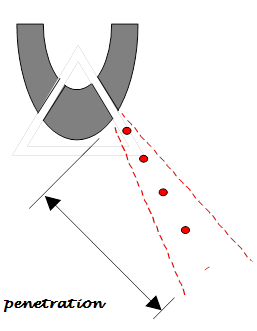
PENETRATION

It refers to the distance that the fuel particles travel or penetrate into combustion chamber

TURBULENCE or SWIRL

– It refers to the aim movement pattern within the combustion chamber at the end of compression.
The spray pattern of the fuel is cone-shaped.
123
– These occurs when there is an excess velocity of fuel spray during injection, causing contact with metallic engine parts and one result is flame burning

INJECTOR NOZZLE:

The body of a fuel injector valve is normally flanged at the upper end and the lower end is threaded to accommodate the nozzle body and nozzle cap nut
The nozzle body contains four holes. One is for the fuel inlet and another for the fuel priming valve, these two holes are connected through a common space within the fuel nozzle or by annular space
images (1)
Image Credit: DieselNet

The valve needle which has been lapped into a very accurately machine guide into the nozzle body, is held on the conical seat immediately above the atomization holes
Slightly clearance between needle and nozzle body to allow for temperature changes when working with heated fuel.

COOLING OF FUEL INJECTION VALVE:

Some injectors have internal cooling passages in them extending into the nozzle through which cooling water is circulated. This is to prevent overheating and burning of the nozzle tip.
Injectors on modern 2 stroke crosshead engines do not have internal water cooling passages. They are cooled by a combination of the intensive bore cooling in the cylinder head being close to the valve pockets and by the fuel which is recirculated through the injector when the follower is on the base of the cam or when the engine is stopped.

As well as cooling the injector, recirculating the fuel when the engine is stopped keeps the fuel at the correct viscosity for injection by preventing it from cooling down.
The animation opposite shows the principle on which one system operates.
Fuel injectors must be kept in good condition to maintain optimum efficiency, and to prevent conditions arising which could lead to damage within the cylinder. Injectors should be changed in line with manufacturers recommendations, overhauled and tested. Springs can weaken with repeated operation leading to the injector opening at a lower pressure than designed. The needle valve and seat can wear which together with worn nozzle holes will lead to incorrect atomisation and dribbling

FAULTS OF FUEL INJECTORS:

1. Over heating OR under cooling:
If cooling of the injector is reduced, either by fuel valve cooling system or poor heat transfer to the cylinder head, then the working temperature of the injector will rise. This can cause:-
– Softening of the needle and seat which increases the possibility of nozzle leakage and/or,
– Fuel to expand/boil out of the fuel sac, leading to carbon trumpet formation, and increased levels of HC and smoke in the exhaust gases.

2. Over cooling:
More common on older vessels with separate fuel valve water cooling systems. When the injector is over cooled, the tip of the injector falls below the condensation temperature and acid corrosion due to the sulphur in the fuel oil occurs. This can severely corrode the injector tip, causing the spray pattern to be affected.

3. leakage from Nozzle:
This fault will produce carbon trumpets as the dribble of fuel burns close to the tip and the carbon deposits remain. The formation of the trumpets will have a progressive affect by influencing the spray pattern of the fuel, and this can be detected in the increased exhaust gas temps and smoke levels.
Nozzle leakage can sometimes be identified by a seat defect(the seat is no longer narrow in appearance, and is caused by):-
– Insufficient cooling,
– Dirt within the fuel damaging/abrading the seating area,
– Excessive needle valve hammering, due to excessive time in service, excessive needle lift or spring force.

4. Weak spring:
This will cause the injector to open and close at a lower pressure. Thus the size of the fuel droplets will increase during these injection periods.
Increased droplet size at the start of combustion will decrease the maximum cylinder pressure (late combustion), whilst increased droplet size at the end of combustion will increase the exhaust temperature and smoke (afterburning).
Causes of a weak spring are usually metal fatigue, due to an excessive number of operations.

5. Slack needle:
Slight leakage between the needle valve and its body is required to provide lubrication of the moving parts. However excess leakage due to a slack needle will allow a greater quantity, and larger size of fuel particle to pass between the valve and body.
The quantity of leakage should not influence injector performance unless excessive, but dirt particles between the needle and body can increase friction and make the needle action sluggish.
The cause of a slack needle is usually poor filtration of the fuel causing wear between needle and body.

6. Poor atomisation:
This will increase the size of the fuel droplets, which will increase the time required for combustion. Thus engine noise, exhaust smoke, exhaust temperatures, etc will increase. Poor atomisation can be caused by low injection pressure (fuel pump wear), high fuel viscosity and nozzle hole obstruction such as carbon trumpets.

7. Poor penetration
This will reduce the mixing which occurs between the fuel and air, and will increase the over-rich areas in the centre area of the cylinder. Thus only following combustion in the centre area will the expanding gases move the fuel charge into the air rich outer ring of the cylinder where the greatest mass of air is present.
This will increase the time required for combustion as the fuel/air mixture is not correct in many areas, and hence afterburning, exhaust temps, and smoke will increase.
Causes of poor penetration is reduced injection pressure, and nozzle hole blockage such as trumpets or sac deposits.

8. Over penetration
This will occur when the air density within the cylinder is reduced, or with over-size holes. The liquid stream travels too far into the cylinder, so that a high level of liquid impingement on the liner wall takes place. This will remove the liner lubrication, and once burning will greatly increase the liner wall temperature, and its thermal stress.
If this over penetration is caused by prolonged low power operations, then “slow speed” nozzles should be fitted.

Slow steaming nozzles can be used when regular and prolonged engine operation is required between 20-50% power.
The nozzle hole diameter is reduced to
i. Reduce the penetration that will occur into the less dense cylinder air
ii. Keep the atomisation level and injection pressure sufficient, as mass flow rate is reduced.

If the engine is operated for long period on low levels of power/speed with `normal’ size injector nozzles, then the atomisation will reduce, thus engine noise, mechanical loading, exhaust smoke, exhaust temps, and fuel consumption will increase.

EFFECT OF FAULTY FUEL INJECTORS:

1. Greatly enlarged holes cause overheating, perhaps burning of piston upper surface, also cause carbon deposits in the piston cooling space, if oil cooled. It may also cause increased cylinder and piston ring wear

2. If the holes are chocked, the fuel sprays will be effected to the extent that imperfect combustion will result. This in turn may reduce the power output quite considerably and bring about all the mechanical troubles usually associated with after burning.
3. If the injectors leaky or spring is damaged, burning of piston upper surface, also cause carbon deposits in the piston cooling space, if oil cooled. It may also cause increased cylinder and piston ring wear and can lead to scavenge fire.

INDICATION OF FAULTS:

1. Early injection is usually evidenced by knocking in the cylinder. On the power diagram the maximum pressure will be considerably in excess. Exhaust temperature will be low.

2. Leaky valve can be detected through indicator diagram, which show reduced combustion pressure. This will be some reduction in power output, increasing in exhaust temperature about 10oC and smoky gases. Chocking of atomizer and exhaust ports. Surging in turbo-blower are also some of the indication

3. After burning will cause higher exhaust temperature and pressure. The maximum height of both the power and draw diagram would be reduced. Other indications are smoky exhaust, possible fires in uptake, fouling of exhaust system, surging of turbo-blower

4. Choked fuel injectors – combustion efficiency of an engine depends on fuel atomization, shape and direction of the fuel sprays. So the holes should be clear and clean. First outward indication of accumulation of carbon deposits will be increase in the exhaust temperature due to fuel not mixing properly with the air, consequently not burning completely in the allocated time. Power output is reduced and the exhaust is smoky.

MAINTENANCE

  • Fuel injectors must be kept in good condition to maintain optimum efficiency, and to prevent conditions arising which could lead to damage within the cylinder.
  • Injectors should be changed in line with manufacturers recommendations, overhauled and tested.
  • Springs can weaken with repeated operation leading to the injector opening at a lower pressure than designed.
  • The needle valve and seat can wear which together with worn nozzle holes will lead to incorrect atomization and dribbling.
  • Proper cooling should be made during operation. Cooling passages to be cleaned during overhaul.
  • Proper grade of fuel oil should be used and it should be used after proper purification to prevent atomized holes become enlarged, conical and oval due to abrasive materials.
  • The valve body and valve needle should always be considered as a unit, not as two separate pieces and they should be renewed together.
  • The holes should be cleaned and cleared properly without damaging by blown with compressed air.
  • The valve needle must be perfectly fluid tight when in the closed position and must open and close smartly.
  • The cam operating the fuel valves or the fuel pump, as the case may be, should effect opening and closing in the shortest time practicable.


References:

1. www.marineengineering.co.uk
2. The Running and Maintenance of Marine Machinery – Cowley
3. Reeds Marine Engineering Series, Vol. 12 – Motor Engineering Knowledge for Marine Engineers
4. Lamb’s Question and Answers on Marine Diesel Engines – S. Christensen
5. Principles and Practice of Marine Diesel Engines – Sanyal

LATEST DEVELOPMENT ON ENERGY-EFFICIENCY IN INTERNATIONAL SHIPPING BY IMO (MEPC 68TH SESSION)

(Energy-efficiency and air pollution implementation at IMO environment meeting, Marine Environment Protection Committee (MEPC), 68th session.11-15 May 2015)

Seagull clean ocean_LA_2
Further development of energy-efficiency guidelines for ships

The MEPC continued its work on further developing guidelines to assist in the implementation of the mandatory energy-efficiency regulations for international shipping and:

• adopted amendments to update the 2014 Guidelines on survey and certification of the Energy Efficiency Design Index (EEDI) and endorsed their application from 1 September 2015, at the same time encouraging earlier application;

• adopted amendments to the 2013 Interim Guidelines for determining minimum propulsion power to maintain the manoeuvrability of ships in adverse conditions, for the level-1 minimum power lines assessment for bulk carriers and tankers, and agreed on a phase-in period of six months for the application of the amendments; and
• adopted amendments to update the 2014 Guidelines on the method of calculation of the attained EEDI for new ships.

EEDI review work to continue

The Committee considered a progress report from the correspondence group established to review the status of technological developments relevant to implementing phase 2 of the EEDI regulations, as required under regulation 21.6 of MARPOL Annex VI and re-established the correspondence group to further the work and submit an interim report to MEPC 69.

Text agreed for further development of a data collection system to analyse the energy efficiency of ships

The MEPC agreed text for its further development to be the full language for the data collection system for fuel consumption of ships, which can be readily used for voluntary or mandatory application of the system. In this regard, the Committee noted that a purpose of the data collection system was to analyse energy efficiency and for this analysis to be effective some transport work data needs to be included, but at this stage the appropriate parameters have not been identified.

The proposed text refers to ships of 5,000 GT and above collecting data, to include the ship identification number, technical characteristics, total annual fuel consumption by fuel type and in metric tons and transport work and/or proxy data yet to be defined. The methodology for collecting the data would be outlined in the ship specific Ship Energy Efficiency Management Plan (SEEMP).

Data would be aggregated into an annual figure and reported by the shipowner/operator to the Administration (flag State) which would submit the data to IMO for inclusion in a database. Access to the database would be restricted to Member States only and data provided to Member States would be anonymized to the extent that the identification of a specific ship would not be possible.

The MEPC agreed to recommend to the IMO Council the holding of an intersessional working group to: further consider transport work and/or proxies for inclusion in the data collection system; further consider the issue of confidentiality; consider the development of guidelines identified in the text; and to submit a report to MEPC 69.

GHG reduction target for international shipping considered

The MEPC considered a submission from the Marshall Islands, calling for a quantifiable reduction target for greenhouse gas emissions from international shipping.

During the discussion, the Member States that spoke acknowledged and recognised the importance of the issues raised by the Marshall Islands and also recognised that, despite the measures already taken by the Organization regarding the reduction of emissions from ships, more could be done.

However, whilst expressing gratitude to the Marshall Islands for the submission, the Committee took the view that the priority at this stage should be to continue its current work, in particular, to focus on further reduction of emissions from ships through the finalization of a data collection system. The Marshall Islands proposal could then be further addressed at an appropriate future session of the Committee. ​The need to consider the proposal further was recognised and the Committee also looked forward to a successful UN climate change conference (UNFCCC COP 21 meeting) in Paris later this year.

Revised air pollution guidance and requirements agreed

The MEPC considered a number of amendments and revisions to existing guidance and requirements related to air pollution measures and in particular:

  • • adopted amendments to the 2009 Guidelines for exhaust gas cleaning systems (resolution MEPC.184(59)). The amendments relate to certain aspects of emission testing, regarding measurements of carbon dioxide (CO2) and sulphur dioxide (SO2), clarification of the washwater discharge pH limit testing criteria and the inclusion of a calculation-based methodology for verification as an alternative to the use of actual measurements;
    • approved, for adoption at MEPC 69, draft amendments to the NOX Technical Code 2008 to facilitate the testing of gas-fuelled engines and dual fuel engines for NOx Tier III strategy;
    • approved, for adoption at MEPC 69, draft amendments to MARPOL Annex VI regarding record requirements for operational compliance with NOX Tier III emission control areas;
    • approved Guidance on the application of regulation 13 of MARPOL Annex VI Tier III requirements to dual fuel and gas-fuelled engines; and
    • adopted amendments to the 2011 Guidelines addressing additional aspects to the NOX Technical Code 2008 with regard to particular requirements related to marine diesel engines fitted with Selective Catalytic Reduction (SCR) Systems (resolution MEPC.198(62)).

The Committee also agreed, for consistency and safety reasons, to proceed with the development of guidelines for the sampling and verification of fuel oil used on board ships.

Fuel oil availability review to be initiated this year

The MEPC agreed terms of reference for the review, required under regulation 14 (Sulphur Oxides (SOx) and Particulate Matter) of MARPOL Annex VI, of the availability of compliant fuel oil to meet the global requirements that the sulphur content of fuel oil used on board ships shall not exceed 0.50% m/m on and after 1 January 2020. The IMO Secretariat was requested to initiate the review by 1 September 2015, with a view to the final report of the fuel oil availability review being submitted to MEPC 70 (autumn 2016) as the appropriate information to inform the decision to be taken by the Parties to MARPOL Annex VI.

A Steering Committee consisting of 13 Member States, one intergovernmental organisation and six international non-governmental organizations was established to oversee the review.

The sulphur content (expressed in terms of % m/m – that is, by weight) of fuel oil used on board ships is required to be a maximum of 3.50% m/m (outside an Emission Control Area (ECA)), falling to 0.50% m/m on and after 1 January 2020. Depending on the outcome of the review, this requirement could be deferred to 1 January 2025. Within ECAs, fuel oil sulphur content must be no more than 0.10% m/m.

Fuel oil quality correspondence group re-established

The MEPC considered the report of the correspondence group established to consider possible quality control measures prior to fuel oil being delivered to a ship. The correspondence group was re-established to: further develop draft guidance on best practice for assuring the quality of fuel oil delivered for use on board ships; further examine the adequacy of the current legal framework in MARPOL Annex VI for assuring the quality of fuel oil for use on board ships; and submit a report to MEPC 69.

Black carbon definition agreed

The MEPC agreed a definition for Black Carbon emissions from international shipping, based on the “Bond et al.” definition which describes Black Carbon as a distinct type of carbonaceous material, formed only in flames during combustion of carbon-based fuel, distinguishable from other forms of carbon and carbon compounds contained in atmospheric aerosol because of its unique physical properties.


For details, please click the below link:
http://www.imo.org/MediaCentre/PressBriefings/Pages/19-MEPC-ends.aspx#.VVvj5_mqqko​​
​​
IMO Briefing: 19, May 18, 2015.
Web site: www.imo.org

WÄRTSILÄ TO DELIVER SCRUBBER SYSTEMS TO CLEAN THE EXHAUST FROM TWO DUTCH RORO CARRIERS

1
Royal Wagenborg, the Dutch ship owner and operator, has ordered Wärtsilä scrubber systems to clean the exhaust emissions from two of its RoRo carriers, the ‘Balticborg’ and ‘Bothniaborg’. These will be Wärtsilä’s first deliveries of its scrubber systems to Royal Wagenborg.


By installing Wärtsilä scrubber systems, the vessels will comply with the regulations covering emissions of sulphur oxides (SOx) while using conventional residual marine fuel (HFO).

The systems chosen for these vessels are Wärtsilä Hybrid Scrubbers, which enable the use of either closed or open loop technology to remove SOx from the exhaust. When operating in open loop mode, exhaust gases enter the system and are sprayed with seawater. The sulphur oxides in the exhaust react with the water to form sulphuric acid. Chemicals are not required since the natural alkalinity of seawater neutralizes the acid. When operating in closed loop mode, the natural alkalinity of seawater is boosted by an alkali. The hybrid approach enables operation in closed loop mode when required, for instance whilst in port and during manoeuvring using NaOH as a buffer. When at sea, the switch can be made to open loop using only seawater.

Wärtsilä Press Release.

WÄRTSILÄ 50DF ENGINE CAPABLES TO OPERATE ON ETHANE GAS

wartsila-50df
The market leading Wärtsilä 50DF marine engine has been successfully tested and certified to run on ethane (LEG) fuel. The extensive and successful testing programme was carried out by Wärtsilä in close collaboration with Evergas, a world renowned owner and operator of seaborne petrochemical and liquid gas transport vessels.


“We are very pleased that the Wärtsilä engines will be capable of utilising ethane boil-off gas as fuel. It increases our operational efficiency and improves flexibility in the bunkering of fuels. All in all it results in a significant reduction in operating costs, while also providing a minimal environmental footprint. It also enables us to offer our customers increased flexibility, which has a monetary value to them,” says Mr Steffen Jacobsen, the CEO of Evergas.

The capability to efficiently burn ethane boil-off gas as engine fuel significantly reduces the need of gas re-liquefaction during the voyage. This means that less power is needed for the cargo handling, thus providing a more efficient and environmentally sound overall system.

This technological breakthrough enables Wärtsilä’s customers to meet the International Maritime Organization’s (IMO) Tier III regulations without need of secondary emissions cleaning while using either LNG or LEG as fuel. The engines have the capability to seamlessly switch between Liquified Natural Gas (LNG), Ethane (LEG), Light Fuel Oil (LFO) or Heavy Fuel Oil (HFO) without the need for any modifications to hardware and with uninterrupted operation, thereby setting a new standard in fuel flexibility.

Wärtsilä press release.

AUDI E-DIESEL- FUEL OF THE FUTURE

audi-fuel
After a commissioning phase of just four months, the research facility in Dresden started producing its first batches of high‑quality diesel fuel a few days ago.
The Dresden energy technology corporation sunfire is Audi’s project partner and the plant operator. It operates according to the power‑to‑liquid (PtL) principle and uses green power to produce a liquid fuel. The only raw materials needed are water and carbon dioxide. The CO2 used is currently supplied by a biogas facility. In addition, initially a portion of the CO2 needed is extracted from the ambient air by means of direct air capturing, a technology of Audi’s Zurich‑based partner Climeworks.

Production of Audi e‑diesel involves various steps: First, water heated up to form steam is broken down into hydrogen and oxygen by means of high-temperature electrolysis. This process, involving a temperature in excess of 800 degrees Celsius, is more efficient than conventional techniques because of heat recovery, for example. Another special feature of high-temperature electrolysis is that it can be used dynamically, to stabilize the grid when production of green power peaks.
In two further steps, the hydrogen reacts with the CO2 in synthesis reactors, again under pressure and at high temperature. The reaction product is a liquid made from long‑chain hydrocarbon compounds, known as blue crude. The efficiency of the overall process – from renewable power to liquid hydrocarbon – is very high at around 70 percent. Similarly to a fossil crude oil, blue crude can be refined to yield the end product Audi e‑diesel. This synthetic fuel is free from sulfur and aromatic hydrocarbons, and its high cetane number means it is readily ignitable. As lab tests conducted at Audi have shown, it is suitable for admixing with fossil diesel or, prospectively, for use as a fuel in its own right.
To demonstrate its suitability for everyday use, Federal Minister of Education and Research Prof. Dr. Johanna Wanka put the first five liters into her official car, an Audi A8 3.0 TDI clean diesel quattro*, this Tuesday. “This synthetic diesel, made using CO2, is a huge success for our sustainability research. If we can make widespread use of CO2 as a raw material, we will make a crucial contribution to climate protection and the efficient use of resources, and put the fundamentals of the “green economy” in place,” declared Wanka.

Audi Press release