Image Credit: www.riceweightloss.com
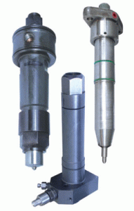
Older loop scavenged engines may have a single injector mounted centrally in the cylinder head. Because the exhaust valve is in the centre of the cylinder head on modern uniflow scavenged engines the fuel valves (2 or 3) are arranged around the periphery of the head.
The pressure at which the injector operates can be adjusted by adjusting the loading on the spring. The pressure at which the injectors operate vary depending on the engine, but can be as high as 540bar.
OPERATION
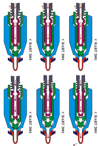
– Fuel injectors achieve this by making use of a spring loaded needle valve.
– The fuel under pressure from the fuel pump is fed down the injector body to a chamber in the nozzle just above where the needle valve is held hard against its seat by a strong spring.
– As the fuel pump plunger rises in the barrel, pressure builds up in the chamber, acting on the underside of the needle as shown. When this force overcomes the downward force exerted by the spring, the needle valve starts to open.
– The fuel now acts on the seating area of the valve, and increases the lift.
– As this happens fuel flows into the space under the needle and is forced through the small holes in the nozzle where it emerges as an “atomised spray”.

Image Credit: www.marinediesels.co.uk
At the end of delivery, the pressure drops sharply and the spring closes the needle valve smartly.
ATOMIZATION

It is the break-up of the fuel change into a very small particles when it is injected into the cylinder
Proper atomization facilitates the starting of the burning and ensures that each minute particle of fuel is surrounded by oxygen particles which it can combine

Image Credit: www.marineinsight.com
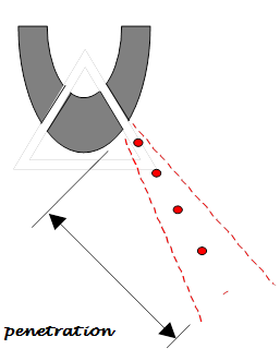
PENETRATION
It refers to the distance that the fuel particles travel or penetrate into combustion chamber

TURBULENCE or SWIRL
– It refers to the aim movement pattern within the combustion chamber at the end of compression.
The spray pattern of the fuel is cone-shaped.

– These occurs when there is an excess velocity of fuel spray during injection, causing contact with metallic engine parts and one result is flame burning
INJECTOR NOZZLE:
The body of a fuel injector valve is normally flanged at the upper end and the lower end is threaded to accommodate the nozzle body and nozzle cap nut
The nozzle body contains four holes. One is for the fuel inlet and another for the fuel priming valve, these two holes are connected through a common space within the fuel nozzle or by annular space

Image Credit: DieselNet
The valve needle which has been lapped into a very accurately machine guide into the nozzle body, is held on the conical seat immediately above the atomization holes
Slightly clearance between needle and nozzle body to allow for temperature changes when working with heated fuel.
COOLING OF FUEL INJECTION VALVE:
Some injectors have internal cooling passages in them extending into the nozzle through which cooling water is circulated. This is to prevent overheating and burning of the nozzle tip.
Injectors on modern 2 stroke crosshead engines do not have internal water cooling passages. They are cooled by a combination of the intensive bore cooling in the cylinder head being close to the valve pockets and by the fuel which is recirculated through the injector when the follower is on the base of the cam or when the engine is stopped.

As well as cooling the injector, recirculating the fuel when the engine is stopped keeps the fuel at the correct viscosity for injection by preventing it from cooling down.
The animation opposite shows the principle on which one system operates.
Fuel injectors must be kept in good condition to maintain optimum efficiency, and to prevent conditions arising which could lead to damage within the cylinder. Injectors should be changed in line with manufacturers recommendations, overhauled and tested. Springs can weaken with repeated operation leading to the injector opening at a lower pressure than designed. The needle valve and seat can wear which together with worn nozzle holes will lead to incorrect atomisation and dribbling
FAULTS OF FUEL INJECTORS:
1. Over heating OR under cooling:
If cooling of the injector is reduced, either by fuel valve cooling system or poor heat transfer to the cylinder head, then the working temperature of the injector will rise. This can cause:-
– Softening of the needle and seat which increases the possibility of nozzle leakage and/or,
– Fuel to expand/boil out of the fuel sac, leading to carbon trumpet formation, and increased levels of HC and smoke in the exhaust gases.
2. Over cooling:
More common on older vessels with separate fuel valve water cooling systems. When the injector is over cooled, the tip of the injector falls below the condensation temperature and acid corrosion due to the sulphur in the fuel oil occurs. This can severely corrode the injector tip, causing the spray pattern to be affected.
3. leakage from Nozzle:
This fault will produce carbon trumpets as the dribble of fuel burns close to the tip and the carbon deposits remain. The formation of the trumpets will have a progressive affect by influencing the spray pattern of the fuel, and this can be detected in the increased exhaust gas temps and smoke levels.
Nozzle leakage can sometimes be identified by a seat defect(the seat is no longer narrow in appearance, and is caused by):-
– Insufficient cooling,
– Dirt within the fuel damaging/abrading the seating area,
– Excessive needle valve hammering, due to excessive time in service, excessive needle lift or spring force.
4. Weak spring:
This will cause the injector to open and close at a lower pressure. Thus the size of the fuel droplets will increase during these injection periods.
Increased droplet size at the start of combustion will decrease the maximum cylinder pressure (late combustion), whilst increased droplet size at the end of combustion will increase the exhaust temperature and smoke (afterburning).
Causes of a weak spring are usually metal fatigue, due to an excessive number of operations.
5. Slack needle:
Slight leakage between the needle valve and its body is required to provide lubrication of the moving parts. However excess leakage due to a slack needle will allow a greater quantity, and larger size of fuel particle to pass between the valve and body.
The quantity of leakage should not influence injector performance unless excessive, but dirt particles between the needle and body can increase friction and make the needle action sluggish.
The cause of a slack needle is usually poor filtration of the fuel causing wear between needle and body.
6. Poor atomisation:
This will increase the size of the fuel droplets, which will increase the time required for combustion. Thus engine noise, exhaust smoke, exhaust temperatures, etc will increase. Poor atomisation can be caused by low injection pressure (fuel pump wear), high fuel viscosity and nozzle hole obstruction such as carbon trumpets.
7. Poor penetration
This will reduce the mixing which occurs between the fuel and air, and will increase the over-rich areas in the centre area of the cylinder. Thus only following combustion in the centre area will the expanding gases move the fuel charge into the air rich outer ring of the cylinder where the greatest mass of air is present.
This will increase the time required for combustion as the fuel/air mixture is not correct in many areas, and hence afterburning, exhaust temps, and smoke will increase.
Causes of poor penetration is reduced injection pressure, and nozzle hole blockage such as trumpets or sac deposits.
8. Over penetration
This will occur when the air density within the cylinder is reduced, or with over-size holes. The liquid stream travels too far into the cylinder, so that a high level of liquid impingement on the liner wall takes place. This will remove the liner lubrication, and once burning will greatly increase the liner wall temperature, and its thermal stress.
If this over penetration is caused by prolonged low power operations, then “slow speed” nozzles should be fitted.
Slow steaming nozzles can be used when regular and prolonged engine operation is required between 20-50% power.
The nozzle hole diameter is reduced to
i. Reduce the penetration that will occur into the less dense cylinder air
ii. Keep the atomisation level and injection pressure sufficient, as mass flow rate is reduced.
If the engine is operated for long period on low levels of power/speed with `normal’ size injector nozzles, then the atomisation will reduce, thus engine noise, mechanical loading, exhaust smoke, exhaust temps, and fuel consumption will increase.
EFFECT OF FAULTY FUEL INJECTORS:
1. Greatly enlarged holes cause overheating, perhaps burning of piston upper surface, also cause carbon deposits in the piston cooling space, if oil cooled. It may also cause increased cylinder and piston ring wear
2. If the holes are chocked, the fuel sprays will be effected to the extent that imperfect combustion will result. This in turn may reduce the power output quite considerably and bring about all the mechanical troubles usually associated with after burning.
3. If the injectors leaky or spring is damaged, burning of piston upper surface, also cause carbon deposits in the piston cooling space, if oil cooled. It may also cause increased cylinder and piston ring wear and can lead to scavenge fire.
INDICATION OF FAULTS:
1. Early injection is usually evidenced by knocking in the cylinder. On the power diagram the maximum pressure will be considerably in excess. Exhaust temperature will be low.
2. Leaky valve can be detected through indicator diagram, which show reduced combustion pressure. This will be some reduction in power output, increasing in exhaust temperature about 10oC and smoky gases. Chocking of atomizer and exhaust ports. Surging in turbo-blower are also some of the indication
3. After burning will cause higher exhaust temperature and pressure. The maximum height of both the power and draw diagram would be reduced. Other indications are smoky exhaust, possible fires in uptake, fouling of exhaust system, surging of turbo-blower
4. Choked fuel injectors – combustion efficiency of an engine depends on fuel atomization, shape and direction of the fuel sprays. So the holes should be clear and clean. First outward indication of accumulation of carbon deposits will be increase in the exhaust temperature due to fuel not mixing properly with the air, consequently not burning completely in the allocated time. Power output is reduced and the exhaust is smoky.
MAINTENANCE
- Fuel injectors must be kept in good condition to maintain optimum efficiency, and to prevent conditions arising which could lead to damage within the cylinder.
- Injectors should be changed in line with manufacturers recommendations, overhauled and tested.
- Springs can weaken with repeated operation leading to the injector opening at a lower pressure than designed.
- The needle valve and seat can wear which together with worn nozzle holes will lead to incorrect atomization and dribbling.
- Proper cooling should be made during operation. Cooling passages to be cleaned during overhaul.
- Proper grade of fuel oil should be used and it should be used after proper purification to prevent atomized holes become enlarged, conical and oval due to abrasive materials.
- The valve body and valve needle should always be considered as a unit, not as two separate pieces and they should be renewed together.
- The holes should be cleaned and cleared properly without damaging by blown with compressed air.
- The valve needle must be perfectly fluid tight when in the closed position and must open and close smartly.
- The cam operating the fuel valves or the fuel pump, as the case may be, should effect opening and closing in the shortest time practicable.
References:
1. www.marineengineering.co.uk
2. The Running and Maintenance of Marine Machinery – Cowley
3. Reeds Marine Engineering Series, Vol. 12 – Motor Engineering Knowledge for Marine Engineers
4. Lamb’s Question and Answers on Marine Diesel Engines – S. Christensen
5. Principles and Practice of Marine Diesel Engines – Sanyal

